Method for the production of a piston for an internal combustion engine and piston for an internal combustion engine

a technology of internal combustion engine and production method, which is applied in the direction of machines/engines, manufacturing tools, electric/magnetic/electromagnetic heating, etc., can solve the problem of not achieving optimal weld connection, and achieve the effect of optimizing the carrying away of heat and pressur

Inactive Publication Date: 2012-02-16
MAHLE INT GMBH
View PDF4 Cites 30 Cited by
  • Summary
  • Abstract
  • Description
  • Claims
  • Application Information

AI Technical Summary

Benefits of technology

[0025]It is advantageous if the constriction extends all the way to the bottom of the cooling channel, in

Problems solved by technology

In this method, however, the joining surfaces cool off after the indu

Method used


Image

  • Method for the production of a piston for an internal combustion engine and piston for an internal combustion engine
  • Method for the production of a piston for an internal combustion engine and piston for an internal combustion engine
  • Method for the production of a piston for an internal combustion engine and piston for an internal combustion engine

Examples


Embodiment Construction

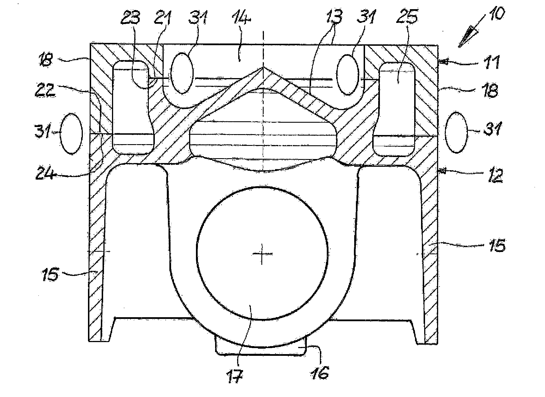
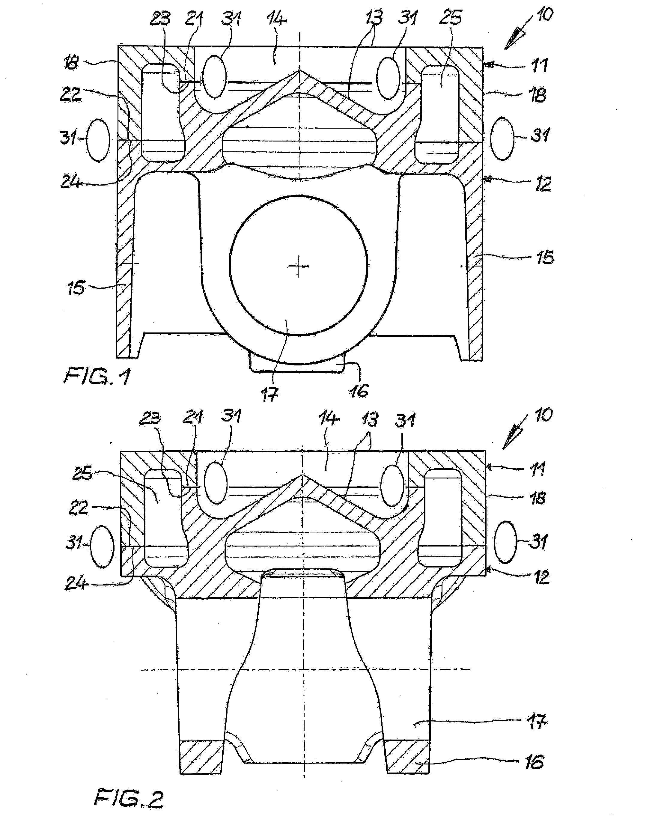
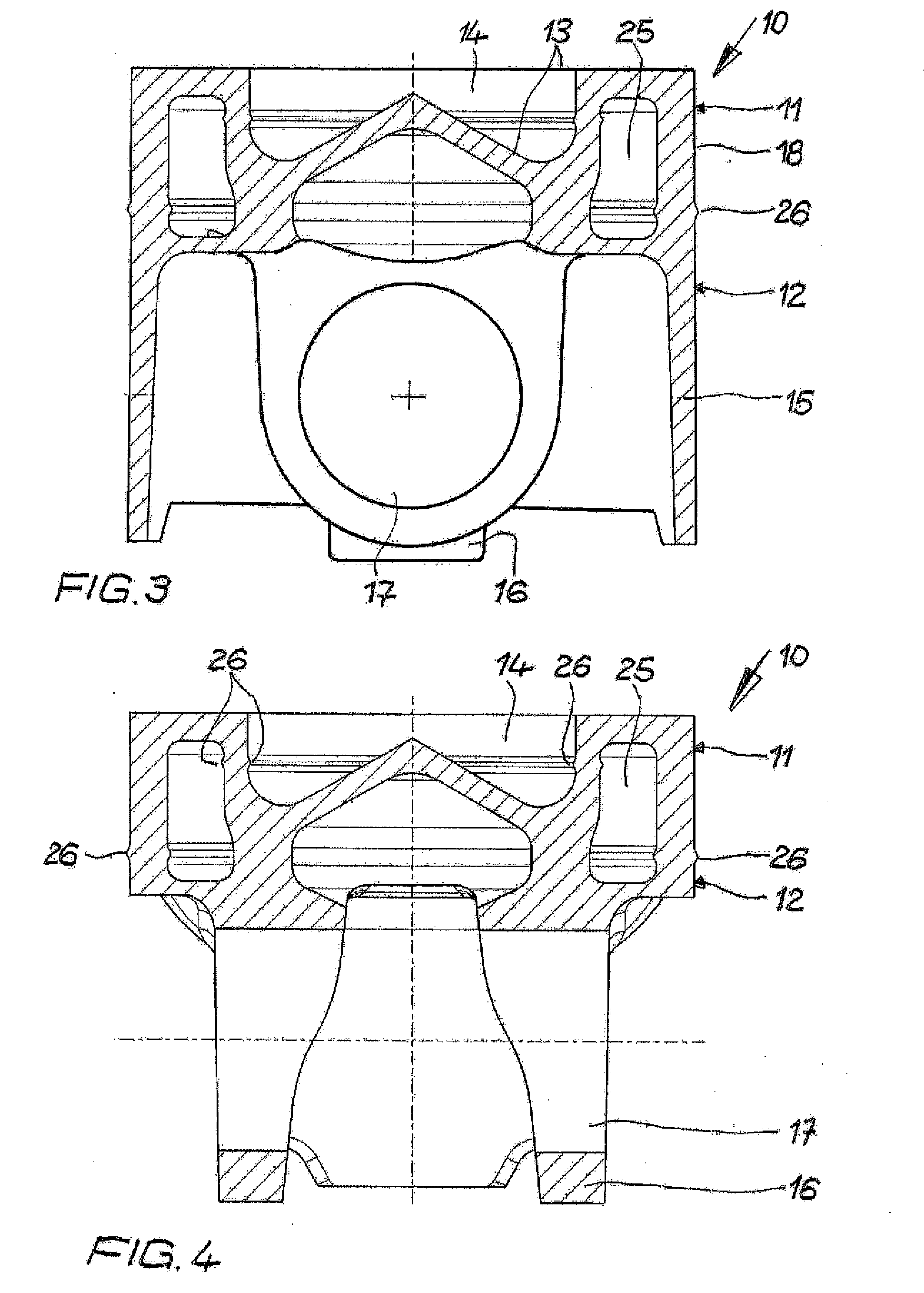
[0038]Referring now in detail to the drawings, FIGS. 1 to 4 show a first exemplary embodiment of a method according to the invention, using a piston 10. The piston 10 is a two-part box piston, having a circumferential cooling channel. However, the present invention is also suitable for other piston types, of course.

[0039]The piston 10 is composed of an upper piston part 11 and a lower piston part 12, which can be produced, for example, from a steel material or a cast iron material, for example by casting or forging. The piston 10 has a piston crown 13 having a combustion bowl 14. Piston crown 13 and combustion bowl 14 are formed partly by the upper piston part 11 and partly by the lower piston part 12. The top land and ring grooves along the outer wall region 18 are not shown, for the sake of clarity. The lower piston part 12 has a piston skirt 15 and pin bosses 16 with pin bores 17 for accommodating a piston pin (not shown).

[0040]The upper piston part 11 has an inner joining surfac...


PUM


Abstract

A method for the production of a piston for an internal combustion engine has the following steps: producing an upper piston part having at least one joining surface, b) producing a lower piston part having at least one joining surface, c) producing a direct contact between the at least one joining surface of the upper piston part and the at least one joining surface of the lower piston part, d) heating the upper piston part and the lower piston part by induction or by a direct flow of current over the joining surfaces in the region of the joining surfaces that have been brought into direct contact, e) connecting the upper and lower piston parts with one another to produce a piston by a pressing process, and machining the piston to finish it.

Description

CROSS REFERENCE TO RELATED APPLICATIONS[0001]Applicants claim priority under 35 U.S.C. §119 of German Application No. 10 2010 033 879.6 filed Aug. 10, 2010, the disclosure of which is incorporated by reference.BACKGROUND OF THE INVENTION[0002]1. Field of the Invention[0003]The present invention relates to a method for the production of a piston for an internal combustion engine.[0004]2. The Prior Art[0005]Such a method is described, for example, in U.S. Pat. No. 6,825,450 B2. An upper piston part and a lower piston part are connected with one another by induction welding, whereby an induction coil is positioned between the joining surfaces of the upper piston part and lower piston part. After the joining surfaces are heated, the induction coil is removed and the weld connection is produced.[0006]In this method, however, the joining surfaces cool off after the induction coil is removed, so that no optimal weld connection is achieved. Furthermore, in this method, the work has to be pe...

Claims


Application Information

Patent Timeline
IPC IPC(8): F02F3/28B23K13/01H05B6/10B21K1/18
CPCB23K11/04B23K2103/06B23K13/06B23K20/023B23K20/028B23K20/12B23K20/129B23K20/227B23K20/24B23P15/10F02F3/003F02F3/22Y10T29/49256B23K2101/003B23K2103/04B23K13/015B23K20/02F02F3/00
Inventor SCHNAITER, FRANKBING, KARLHEINZSCHARP, RAINER
Owner MAHLE INT GMBH
Why Eureka
Try Eureka