Blade of crosscut shredder

a shredding blade and cross-cut technology, applied in the field of shredding blades, can solve the problems of saving machining costs and one serious drawback of cross-cut shredding blades, and achieve the effect of reducing the motor load

Inactive Publication Date: 2012-02-16
MICHILIN PROSPERITY
View PDF1 Cites 4 Cited by
  • Summary
  • Abstract
  • Description
  • Claims
  • Application Information

AI Technical Summary

Benefits of technology

[0008]In view of the foregoing, an objective of the invention is to provide a revolutionary crosscut shredding blade and, in particular, a crosscut blade that can effectively reduce the motor load.
[0012]When the blades rotate with the rotary shafts in opposite directions, the auxiliary shoots on any blade of either rotary shaft push the paper toward the primary shoots on the corresponding blade on the other rotary shaft. The primary shorts can thus pierce the paper at a lower power consumption.

Problems solved by technology

However, blades made by stamping are usually sharp only on one side to save the machining cost.
This is one serious drawback of the crosscut shredding blades.

Method used


Image

  • Blade of crosscut shredder
  • Blade of crosscut shredder
  • Blade of crosscut shredder

Examples


Embodiment Construction

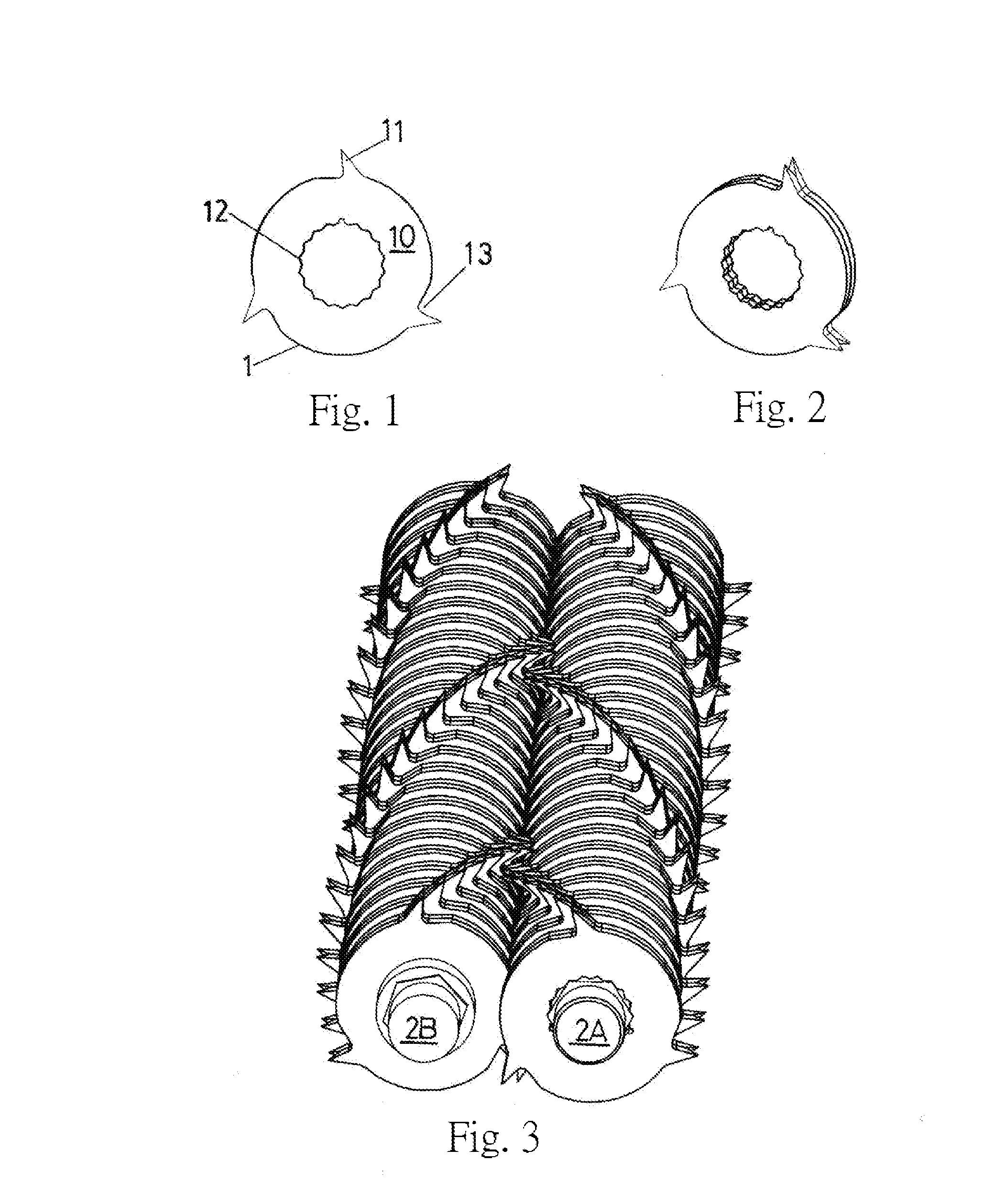
[0027]The present invention will be apparent from the following detailed description, which proceeds with reference to the accompanying drawings, wherein the same references relate to the same elements.

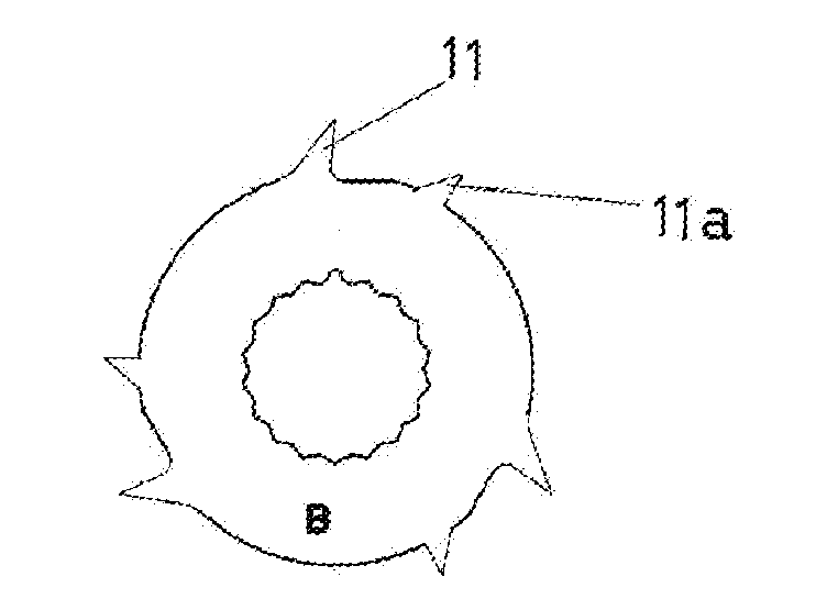
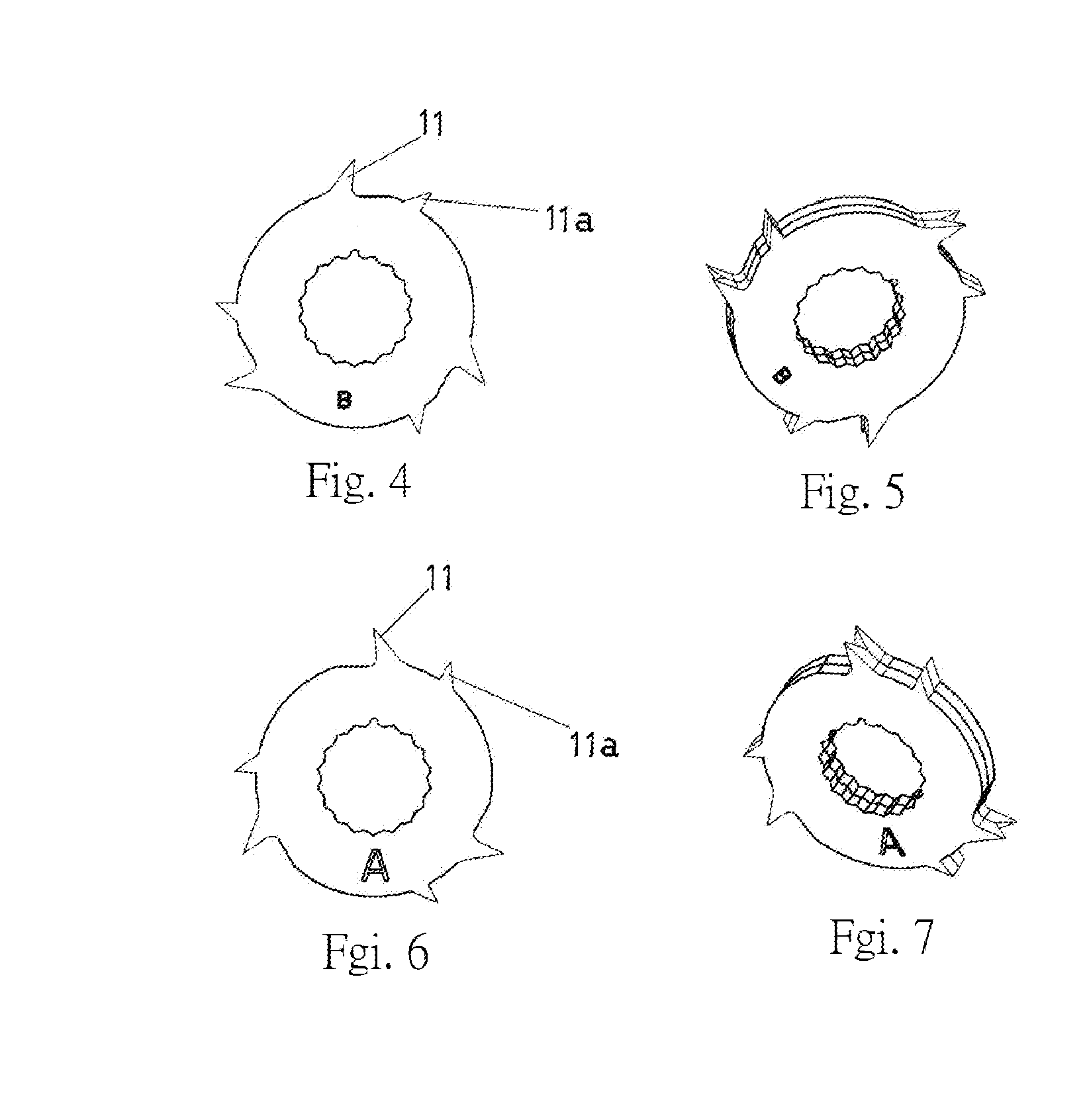
[0028]FIG. 4 shows a first blade B. As shown in FIG. 5, two of the first blades are combined to form a first blade set. Several first blade sets are mounted on the rotary shaft 2B on the left-hand side through the multi-tooth hole in a spiral way, as shown in FIG. 8. The rotary shaft 2B rotates clockwise when the shredder is in the shredding mode (AUTO). FIG. 6 shows a second blade A. As shown in FIG. 7, two of the second blades are combined to form a second blade set. Several second blade sets are mounted on the rotary shaft 2A on the right-hand side through the multi-tooth hole in a spiral way, as shown in FIG. 8. The rotary shaft 2A rotates counterclockwise when the shredder is in the shredding mode (AUTO).

[0029]The first blade B and the second blade A differ from the traditional b...


PUM


Abstract

A blade of the crosscut shredder has the feature that any of a plurality of blades on rotary shafts rotating in opposite directions has a plurality of primary shoots. A plurality of auxiliary shoots are provided in the vicinity of the primary shoot. The distance between the primary shoot and the blade center is slightly larger than the distance between the auxiliary shoot and the blade center. When the blades rotate in opposite directions with the rotary shafts, the auxiliary shoots of any blade on either rotary shaft pushes the paper to be shredded toward the primary shoots on the opposite blade. The primary shoots thus pierce the paper at a lower power.

Description

BACKGROUND OF THE INVENTION[0001]1. Field of Invention[0002]The invention relates to a shredder and, in particular, to an improved shredding blade that can reduce the load of the shredder motor.[0003]2. Related Art[0004]To prevent such documents as legal files, receipts, invoices, credit card numbers, research reports, or personal financial information (e.g., credit card and phone bills) from being released, it is common to destroy them using a shredder. Therefore, the shredder has become an indispensable device for both business and home applications.[0005]The working principle of a crosscut shredder is to mount several blades on two parallel rotary shaft rotating in opposite directions. A motor and a gearbox are used to rotate the rotary shafts, thereby cutting paper into chips and dropping them into a trash bin.[0006]The traditional shredding blade 1 shown in FIG. 1 includes a blade flank 10 to cut the paper longitudinally into stripes and shoots 11 to pierce paper. As shown in F...

Claims


Application Information

Patent Timeline
Patent Type & Authority Applications(United States)
IPC IPC(8): B02C18/18
CPCB02C18/142B02C18/182
Inventor PAN, PETER
Owner MICHILIN PROSPERITY
Why Eureka
Try Eureka