
Device for controlling motor in washing machine and method for controlling process of washing machine by using the same

a technology of washing machine and motor, which is applied in the direction of other washing machines, textile parts treatment, sustainable buildings, etc., can solve the problems of inability to implement a variety of algorithms and inability to cope with load variation, so as to reduce the load of the motor and enhance the energy efficiency

Active Publication Date: 2007-11-27
LG ELECTRONICS INC
View PDF28 Cites 1 Cited by
  • Summary
  • Abstract
  • Description
  • Claims
  • Application Information

AI Technical Summary

Benefits of technology

[0017]An object of the present invention is to provide a device for controlling a motor in a washing machine and a method for controlling a process of a washing machine by using the same, in which a rotation torque of a motor is varied with a user set process mode and kind of introduced laundry, for carrying out an optimal washing process, reducing a motor load, and enhancing an energy efficiency.
[0031]The ‘mode change rinsing’ includes a first step for carrying out spinning for a preset time period after draining, a second step for carrying out a general rinsing by rotating the pulsator in regular / reverse directions for a preset time period after water supply when the preset time period for the first step is passed, a third step for carrying out a general rinsing for a preset time period with the rotation torque of the motor increased when the preset time period for the second step is passed, and a fourth step for carrying out the second step with the rotation torque of the motor reduced when the preset time period for the third step is passed.

Problems solved by technology

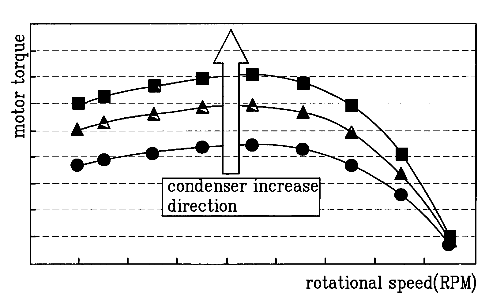
Since the condenser capacity is not variable once fixed in the related art washing machine, unable to vary the torque at a given rotational speed, it has been impossible to implement a variety of algorithm.
Moreover, since the torque of the induction motor is not variable, it has been impossible to cope with load variation following rotation of the pulsator in a washing cycle, and rotation both of the inner tub and the pulsator in the spinning cycle.

Method used


Image

  • Device for controlling motor in washing machine and method for controlling process of washing machine by using the same
  • Device for controlling motor in washing machine and method for controlling process of washing machine by using the same
  • Device for controlling motor in washing machine and method for controlling process of washing machine by using the same

Examples


first embodiment

[0059]Referring to FIG. 5, when the user's selection process mode is an algorithm including ‘a mode change general washing’, in the method of controlling ‘the mode change general washing’, a washing cycle is carried out in a first mode for a preset time period (S10˜S11). In the washing cycle, a washing is carried out as rotation of the motor 10 is transmitted to the washing shaft 3b and 3c in a state the clutch 6 is moved up, to rotate the pulsator 3a only.

[0060]The motor 10 is made to stop temporarily after the preset time period is passed, stop of the pulsator 3a is determined, and a capacity of the condenser is increased after stop of the pulsator 3a is confirmed (S12˜S14).

[0061]Then, the torque of the motor 10 is changed according to the increased capacity of the condenser in rotation of the pulsator 3a only in a second mode for a preset time period in carrying out the washing cycle (S15).

[0062]In this instance, a torque of the induction motor 10 in the second mode is higher tha...

second embodiment

[0066]Referring to FIG. 6, when the user's selection process mode is an algorithm including ‘a tub washing’, in the method of controlling ‘the tub washing’, a general washing cycle is carried out at first, during which change to a tub washing is determined (S20˜S21). In the general washing cycle, a washing is carried out as rotation of the motor 10 is transmitted to the washing shaft 3b and 3c in a state the clutch 6 is moved up, to rotate the pulsator 3a only. In this instance, the third switch 13 is in a turned off state.

[0067]Then, when it is a time to change to the tub washing, for an example, when a preset time period of the general washing is passed, the motor 10 is stopped, and after stop of the pulsator 3a is confirmed, the clutch 6 is moved down and, at the same time with this, capacity of the condenser is increased (S22˜S25).

[0068]Then, after releasing a brake (not shown) having the inner tub 2 held thereto, the tub washing is carried out (S26˜S27). The tub washing cycle i...

third embodiment

[0071]Referring to FIG. 7, when the user's selection process mode is an algorithm including ‘a penetration (alpha) washing’, in the method of controlling ‘the penetration washing’, a general washing cycle is carried out at first, during which change to the penetration washing is determined (S30˜S31). In the general washing cycle, a washing is carried out as rotation of the induction motor 10 is transmitted to the washing shaft 3b and 3c in a state the clutch 6 is moved up, to rotate the pulsator 3a only in regular / reverse directions. In this instance, the third switch 13 is in a turned off state.

[0072]Then, when it is a time to change to the penetration washing (for an example, when a preset time period of the general washing is passed), the motor 10 is stopped, and after stop of the pulsator 3a is confirmed, the clutch 6 is moved down and, at the same time with this, capacity of the condenser is increased (S32˜S35).

[0073]Then, after releasing a brake (not shown) having the inner tu...


PUM


Abstract

Device for controlling a motor in a washing machine and a method for controlling a process of a washing machine by using the same, the device including a motor, a power source part for supplying a voltage to the motor, a plurality of torque varying parts parallel to each other and electrically connected to the motor for varying a rotation torque of the motor, a plurality of switching part connected to the torque varying parts respectively and electrically connected to the power source part, a driving part for switching the switching parts, and a controlling part for controlling the driving part so as to vary the rotation torque of the motor according to a mode of user's selection.

Description

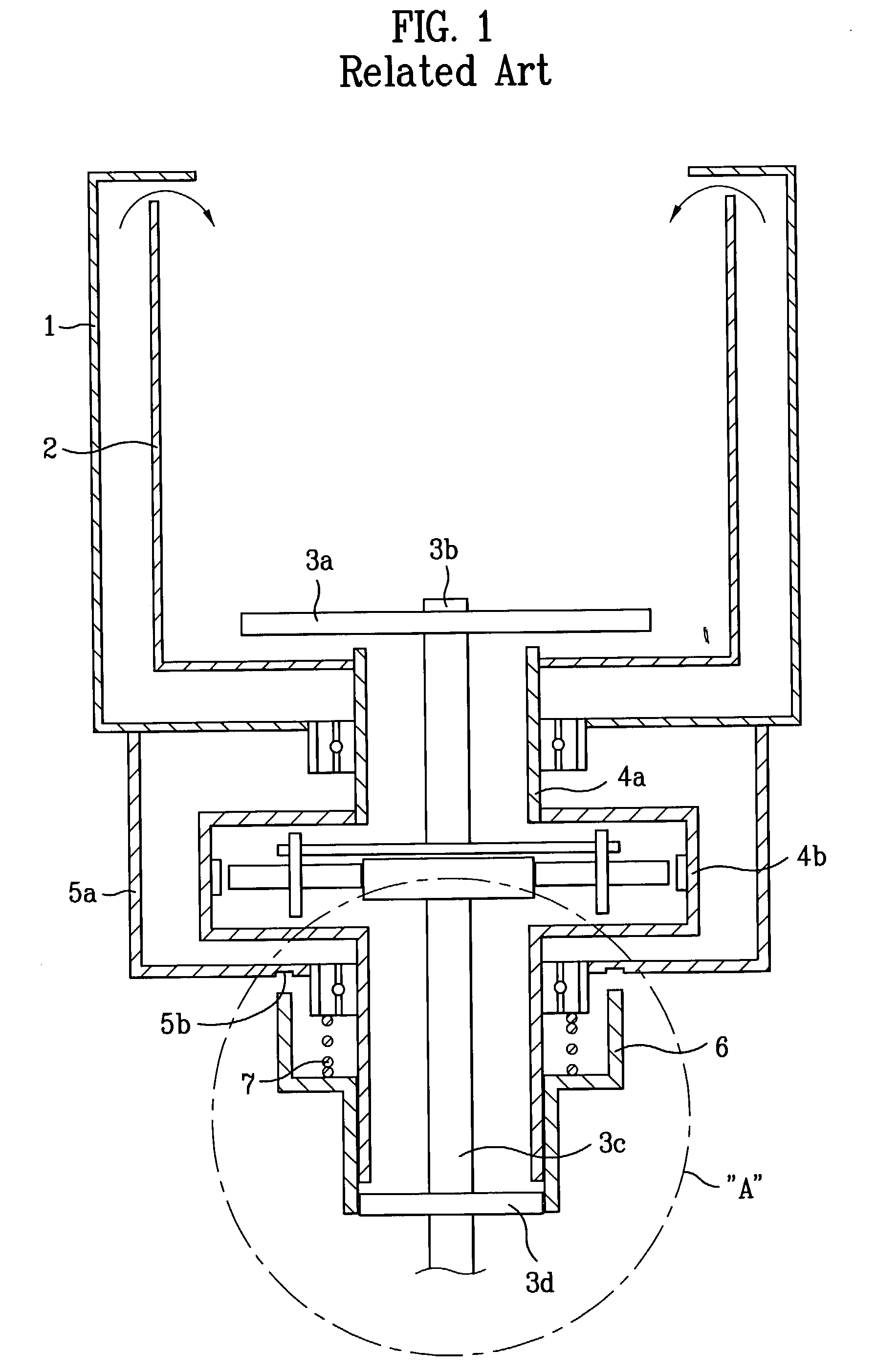
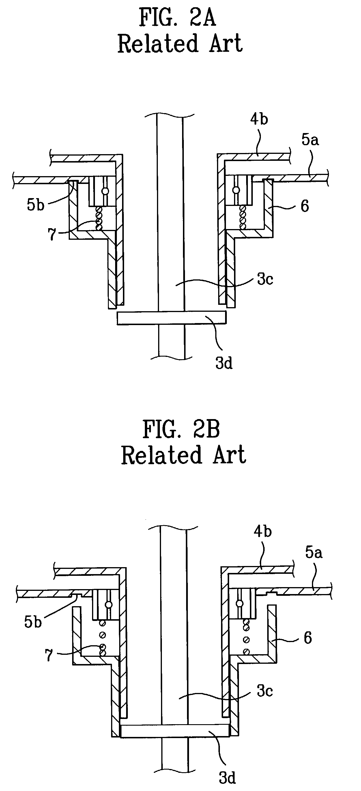
[0001]This application claims the benefit of the Korean Application No. P2002-29840 filed on May 29, 2002, which is hereby incorporated by reference.BACKGROUND OF THE INVENTION[0002]1. Field of the Invention[0003]The present invention relates to a device for controlling a motor in a washing machine and a method for controlling a process of a washing machine by using the same.[0004]2. Background of the Related Art[0005]In general, the washing machine is a home appliance for washing laundry by friction caused by circulation of washing water occurred as the washing water is forced circulated, and softening action of detergent, and has in general, washing, rinsing, and spinning cycles.[0006]The washing machine illustrated in FIG. 1 is provided with a washing shaft divided into an upper washing shaft 3b and a lower washing shaft 3c. The upper washing shaft 3b has a pulsator 3a connected to a top end thereof, and the lower washing shaft 3c has a pulley boss 3d connected to a lower end the...

Claims


Application Information

Patent Timeline
Patent Type & Authority Patents(United States)
IPC IPC(8): D06F33/02D06F37/30
CPCD06F37/304Y02B40/52D06F2214/00D06F2204/10Y02B40/00D06F34/10D06F2105/46D06F2101/14
Inventor CHANG, BO YOUNGLIM, HEE TAECHOI, BYUNG KEOLPARK, SEUNG CHULKIM, DONG WON
Owner LG ELECTRONICS INC
Learn More