Method for controlling a brushless electric motor

a brushless electric motor and electric motor technology, applied in the direction of motor/generator/converter stopper, electronic commutator control, motor/generator/converter stopper, etc., can solve the problem of thermal overload of the motor, the rotational speed of the uncontrolled motor rises, and the motor load increases. the effect of increasing the pwm ratio, reducing the load of the motor, and rotating more slowly

Active Publication Date: 2005-10-20
MINEBEAMITSUMI INC
View PDF14 Cites 1 Cited by
  • Summary
  • Abstract
  • Description
  • Claims
  • Application Information

AI Technical Summary

Benefits of technology

[0014] If the supply voltage falls below the nominal voltage at full motor load, the control rapidly reaches the maximum PWM ratio. From this point on, the PWM ratio cannot be increased any further, which is why the input current cannot rise any further either. Instead, due to the reduced voltage and the consequent decline in current consumption, the motor rotates more slowly and the motor load also decreases (power loss).

Problems solved by technology

As the supply voltage increases, the rotational speed of the uncontrolled motor rises.
As a result, the load on the motor also increases which means that thermal overloading of the motor can easily occur if the supply voltage is too high.
What is more, as the rotational speed increases, not only does the load on the motor increase but also the noise of the fan.
This increase in load not only means an increase in energy consumption, but also increased motor self-heating, which in turn has a negative impact on the useful life of the bearing system.
Hence a decrease in the supply voltage leads to an increase in current consumption, which means that the power electronics, in particular, have to be designed for these currents.
Problems could occur, however, for motors having integrated commutation electronics since the power electronics have to deliver constant power even at a reduced supply voltage and thus consume a higher current as shown in the following table: Supply voltageInput current−10%+11%−20%+25%−30%+43%
The power loss, i.e. the thermal load on the power semiconductors of the commutation electronics, also increases to a corresponding extent.
This, however, goes to increase the costs of the sensors, which means that this kind of solution is generally out of the question for low-cost motors due to the expenses involved.
Instead, due to the reduced voltage and the consequent decline in current consumption, the motor rotates more slowly and the motor load also decreases (power loss).

Method used


Image

  • Method for controlling a brushless electric motor
  • Method for controlling a brushless electric motor
  • Method for controlling a brushless electric motor

Examples


Embodiment Construction

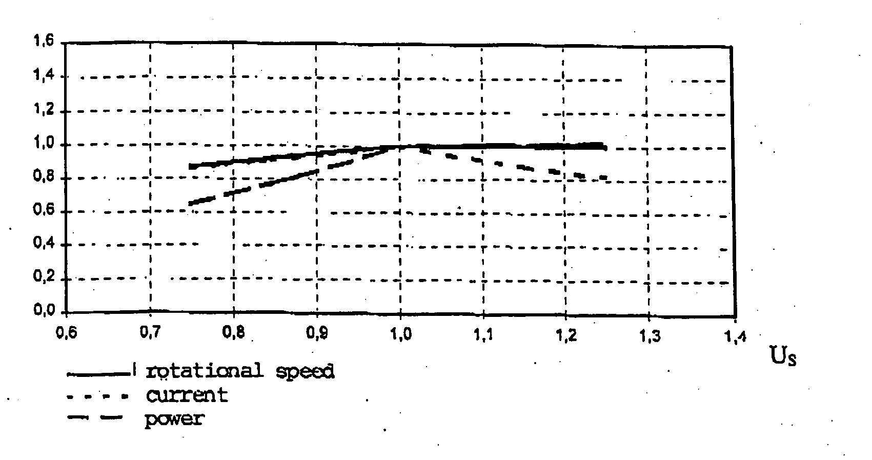
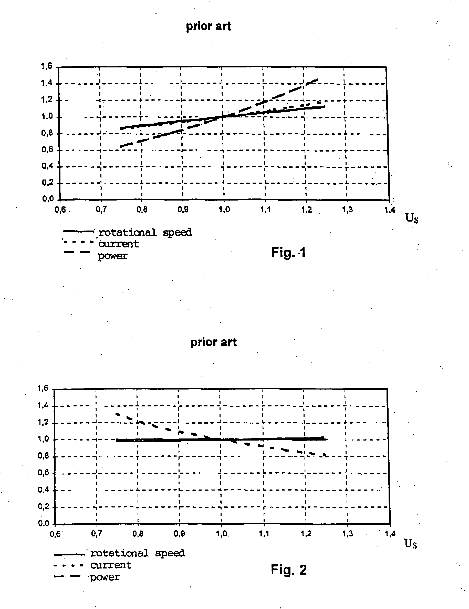
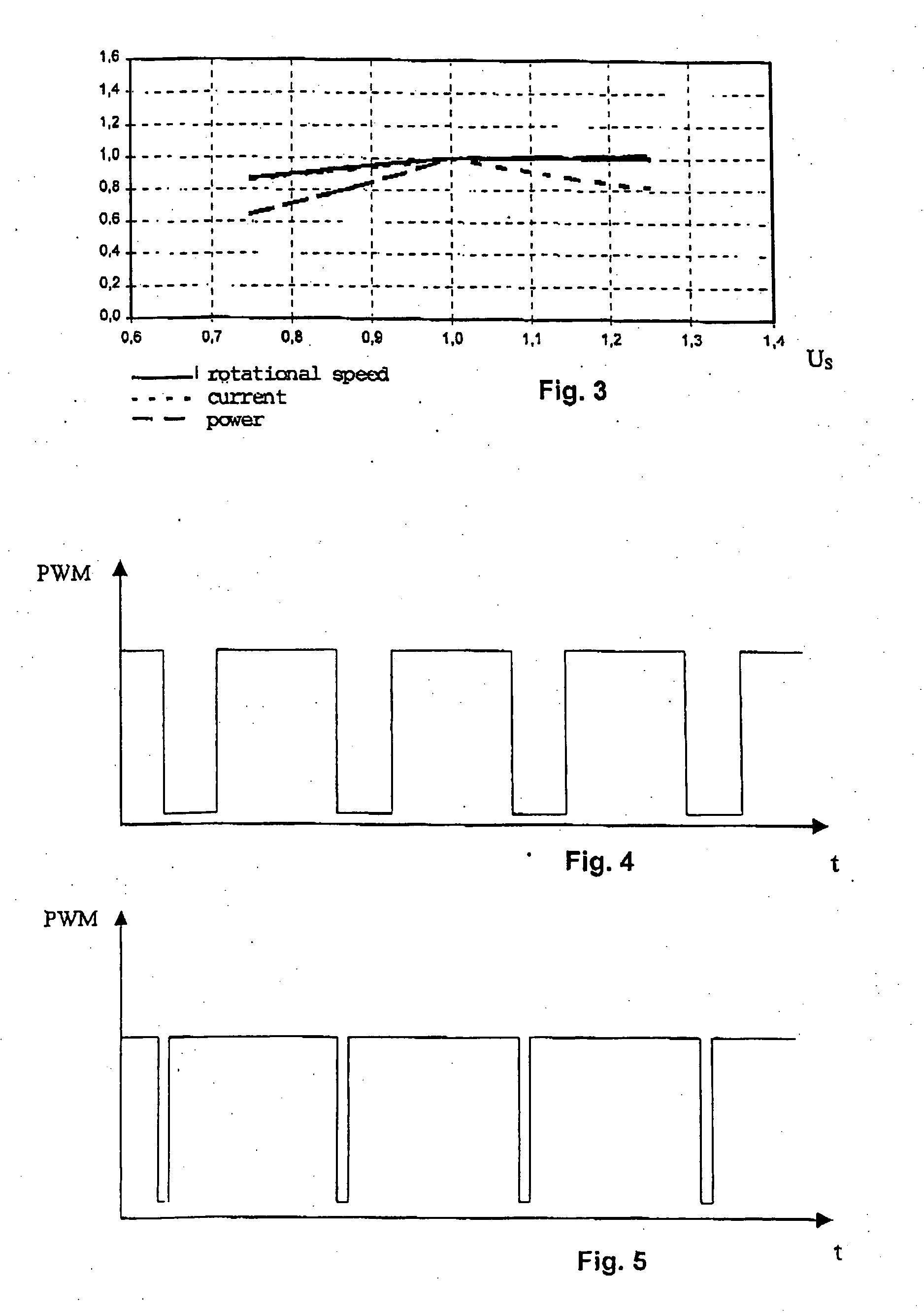
[0021] In FIGS. 1 to 3, the rotational speed is shown as an unbroken line, the current as a dotted line and the power as a dashed line, plotted against the voltage. The parameters have been normalized to the nominal speed, the nominal current and the nominal power as well as the nominal voltage.

[0022]FIG. 1 shows a diagram of the relative speed, motor current and input power (nominal value=1.0) of a brushless fan drive without a closed-loop control according to the prior art, as a function of the relative supply voltage (nominal value=1.0). It can be clearly seen that all values show an approximately linear growth as the supply voltage increases.

[0023] This results in an increase in energy consumption, higher losses in the motor and in the commutation electronics, as well as an increase in flow noise, particularly when the supply voltage is higher than the nominal voltage (1.0).

[0024]FIG. 2 shows a diagram of the relative speed, motor current and input power of a brushless fan dr...


PUM


Abstract

The invention relates to a method for controlling a brushless electric motor for operation within a specified supply voltage range, a motor control controlling the winding voltage by means of pulse width modulation (PWM) and regulating the rotational speed to a specified speed. According to the invention, the motor is so rated that the nominal rotational speed is just achieved at the nominal operating point at the nominal supply voltage and at the maximum PWM ratio.

Description

BACKGROUND OF THE INVENTION [0001] The invention relates to a method for controlling a brushless electric motor according to the preamble of patent claim 1. Prior art [0002] Brushless DC motors for applications in fans, operating with or without a closed-loop control, are known. [0003] The rotational speed of a brushless DC motor that does not have a closed-loop control is dependent on the supply voltage (see FIG. 1). The higher the supply voltage, the higher is the rotational speed of the motor. In some applications, for example in motor vehicles, fan motors having a nominal supply voltage of 12 V are used. The on-board voltage of motor vehicles, however, can vary, ranging between 8 V and 18 V, which means that the rotational speed of the motor can also fluctuate greatly. In fan applications, the mechanical power output rises at approximately the cube of the rotational speed. As the supply voltage increases, the rotational speed of the uncontrolled motor rises. As a result, the loa...

Claims


Application Information

Patent Timeline
Patent Type & Authority Applications(United States)
IPC IPC(8): H02P6/06H02P6/00H02P6/08H02P6/16H02P6/18
CPCH02P6/001H02P6/34
Inventor LELKES, ANDRASBUFE, MICHAEL
Owner MINEBEAMITSUMI INC
Why Eureka
Try Eureka