

Three-mirror anastigmat with at least one non-rotationally symmetric mirror
a three-mirror anastigmat and mirror technology, applied in the field of reflecting optical systems, can solve the problems of image defocus, inability to design refractive objective optical systems with multi-waveband imaging capability, additional demands on the objective optical system, etc., and achieve distortion correction and minimize residual image aberration
- Summary
- Abstract
- Description
- Claims
- Application Information
AI Technical Summary
Benefits of technology
Problems solved by technology
Method used
Image

Examples
embodiment 1
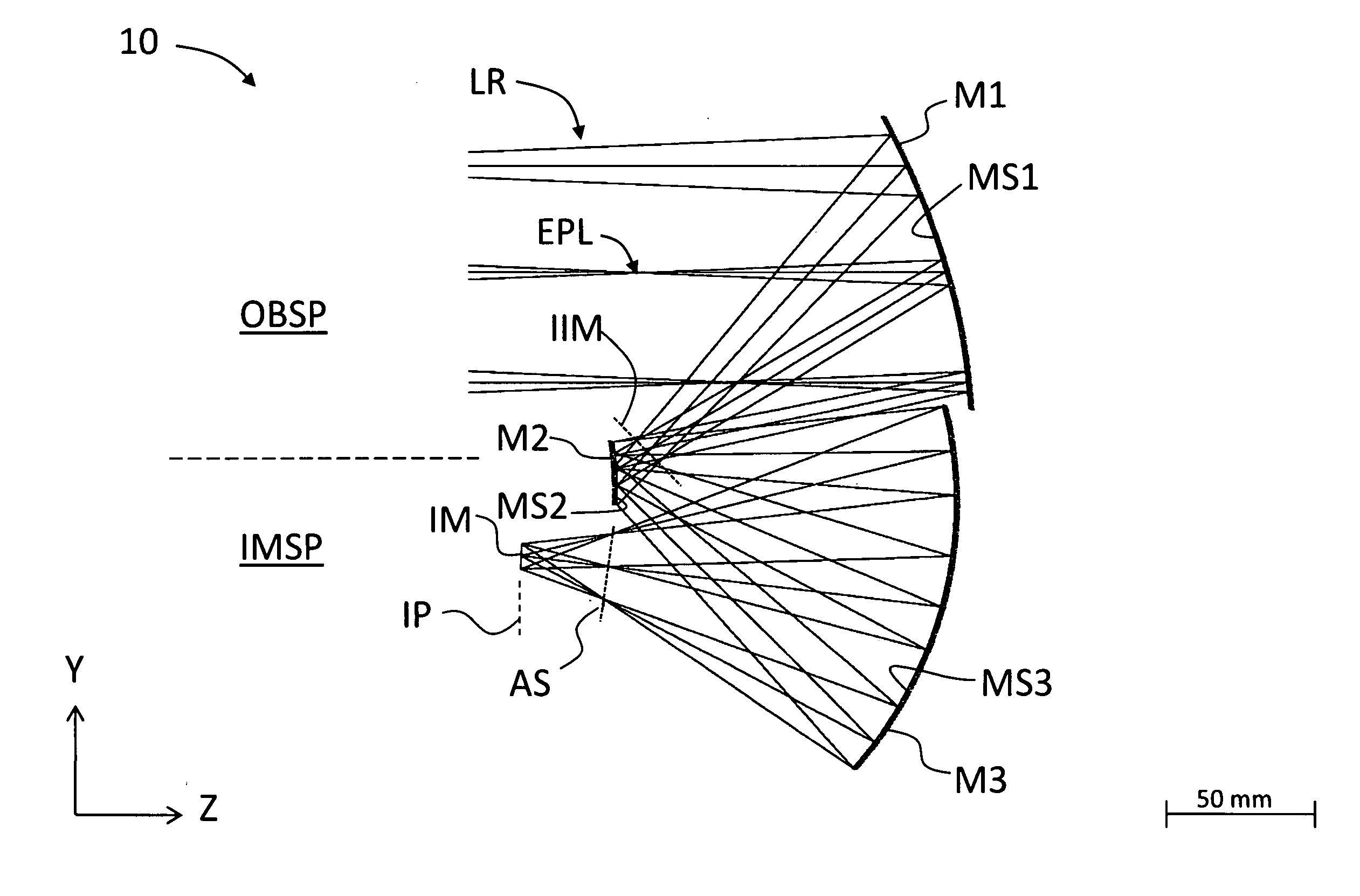
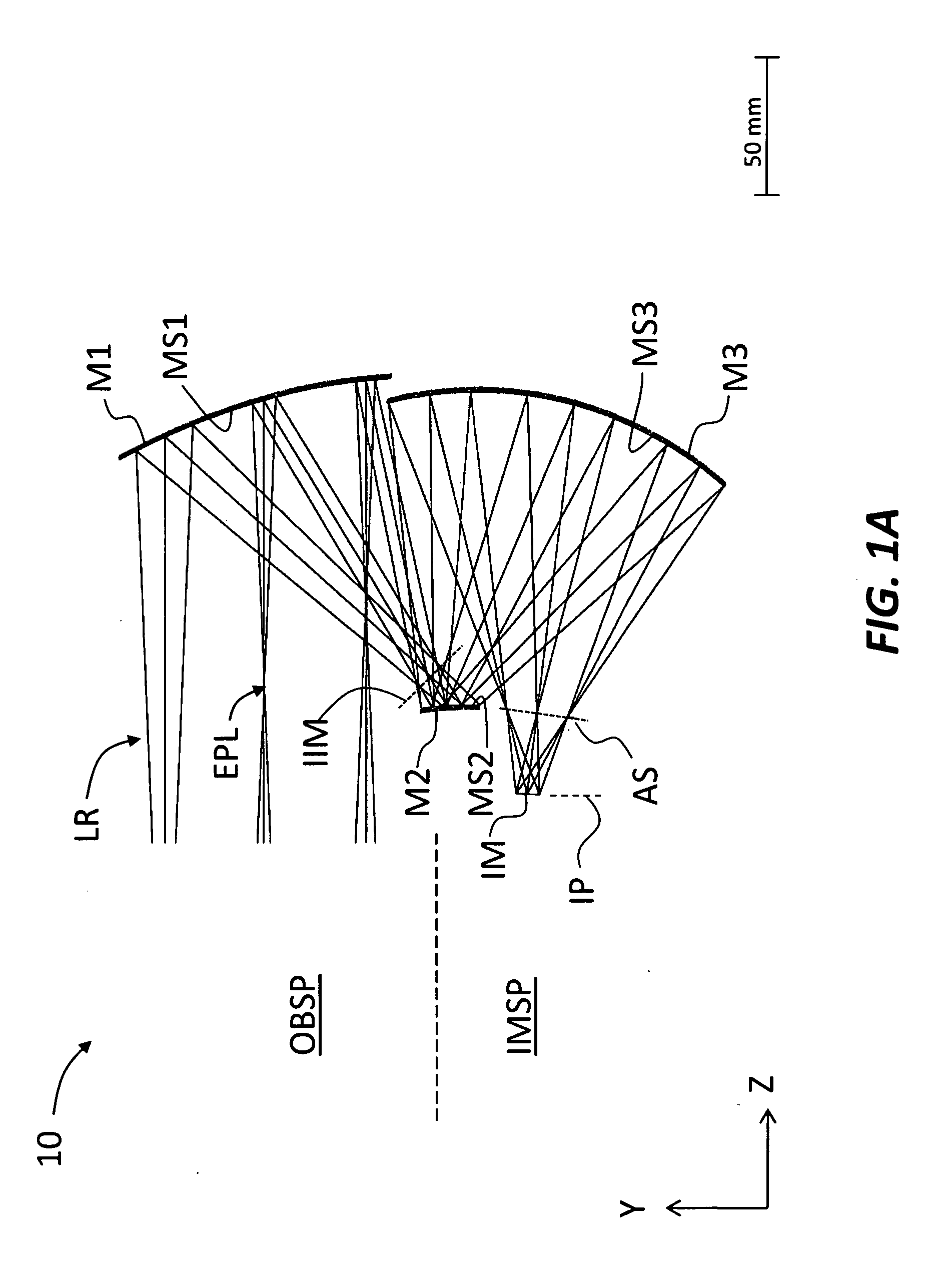
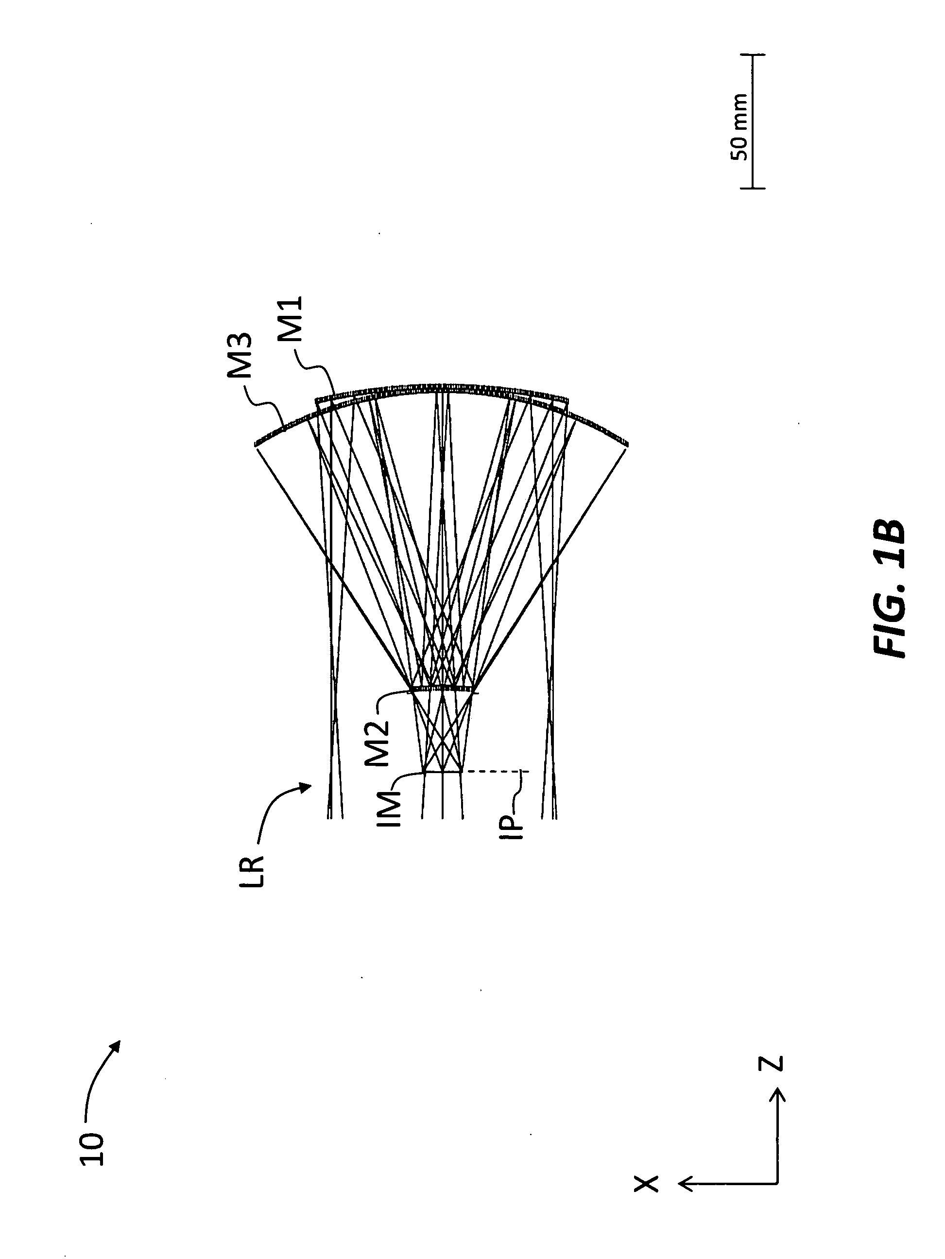
[0048]FIG. 1A and FIG. 1B are YZ and XZ schematic diagrams of a first example embodiment of a TMA system (“system”) 10 operating at a full aperture of approximately f / 1.3. TMA system 10 includes a first (primary) mirror M1 having a reflective surface MS1, a second (secondary) mirror M2 having a reflective surface MS2, and a third (tertiary) mirror M3 having a reflective surface MS3. Mirrors M1, M2 and M3 are arranged in a TMA configuration that is off-axis and decentered in the YZ plane.
[0049]Light rays LR are shown as initially traveling from left to right from an object space OBSP and are first incident upon primary mirror M1. Primary mirror M1 reflects light rays LR to secondary mirror M2, which in turn reflects the light rays to tertiary mirror M3. Tertiary mirror M3 directs the light rays to an image plane IP in image space IMSP to form an image IM at the image plane. An aperture stop AS is located between the tertiary mirror M3 and image plane IP.
[0050]An entrance pupil is loc...
embodiment 2
[0078]FIG. 3A and FIG. 3B are YZ and XZ schematic diagrams of a second example embodiment of TMA system 10 similar to that of FIGS. 1A and 1B, and operating at a full aperture of approximately f / 2 and having no signature augmentation.
TABLE 2SECOND EMBODIMENT LENS DESIGN PRESCRIPTIONITEMRYRXXPYPZPXRYRZROBJ SRFFlatFlat0.00000.0000Infinity0.00000.00000.0000REF SRFFlatFlat0.00000.00000.00000.00000.00000.0000M1−205.1044−222.80250.0000−5.0000120.0000−8.57650.00000.0000M2−113.0176−130.10150.0000−8.41660.8700−5.19960.00000.0000M3−140.2746−136.59950.0000−6.0545117.3128−5.02260.00000.0000ASFlatFlat0.0000−20.2894−1.8286−18.17780.00000.0000IM SRFFlatFlat0.0000−10.6175−31.31674.73850.00000.0000
[0079]The coefficients for mirror M1 are:
CY = −0.00487556KY = −0.686247CX = −0.00448828KX = −0.654082AR = −1.90716E−10BR = −6.75685E−18CR = 1.08161E−23DR = 1.16122E−20AP = 4.30883E−01BP = −2.90298E+00CP = −9.15213E+00DP = −1.02112E+00
[0080]The coefficients for mirror M2 are:
CY = −0.00884818KY = 0.000000CX ...
embodiment 3
[0087]FIG. 4A and FIG. 4B are YZ and XZ schematic diagrams of a third example embodiment of TMA system 10 similar to that of FIGS. 1A and 1B, and operating at a full aperture of approximately f / 2.5 and having no signature augmentation and very well corrected distortion.
TABLE 3THIRD EMBODIMENT LENS DESIGN PRESCRIPTIONITEMRYRXXPYPZPXRYRZROBJ SRFFlatFlat0.00000.0000Infinity0.00000.00000.0000REF SRFFlatFlat0.00000.00000.00000.00000.00000.0000M1−253.6653−276.13660.0000−11.0984131.5668−11.13810.00000.0000M2−393.8576−114.41490.0000−22.6815−15.6488−2.76830.00000.0000M3−192.5621−185.37620.0000−14.9896146.9573−8.11340.00000.0000ASFlatFlat0.0000−28.62873.7728−4.68910.00000.0000IM SRFFlatFlat0.0000−11.4359−46.5678−1.22540.00000.0000
[0088]The coefficients for mirror M1 are:
CY = −0.00394220KY = −0.607722CX = −0.00362140KX = −0.718760AR = −1.28028E−09BR = −6.59389E−17CR = −9.64461E−23DR = −6.95582E−26AP = 1.19682E−02BP = −6.71175E+00CP = −9.25230E+00DP = −3.07606E+00
[0089]The coefficients for mirr...
PUM
 Abstract
Description
Claims
Application Information