Cardiac computed tomography methods and systems using fast exact/quasi-exact filtered back projection algorithms

a computed tomography and fast technology, applied in tomography, instruments, applications, etc., can solve the problems of insufficient development of reliable diagnosis and therapy, cumbersome reconstruction of key subject areas such as the heart, lung, head and neck, etc., to and improve the accuracy of image prediction

Inactive Publication Date: 2012-02-16
VIRGINIA TECH INTPROP INC
View PDF12 Cites 15 Cited by
  • Summary
  • Abstract
  • Description
  • Claims
  • Application Information

AI Technical Summary

Benefits of technology

[0015]The numerous limitations inherent in the scanning systems described above provide great incentive for new, better systems and methods capable of accounting for one or more of these issues. If CTs are to be...

Problems solved by technology

The primary limitation to the above-mentioned system is its need to provide good temporal resolution and image reconstruction when movement is involved.
However, as more complex applications for scanning are encountered, reconstruction of key subjec...

Method used


Image

  • Cardiac computed tomography methods and systems using fast exact/quasi-exact filtered back projection algorithms
  • Cardiac computed tomography methods and systems using fast exact/quasi-exact filtered back projection algorithms
  • Cardiac computed tomography methods and systems using fast exact/quasi-exact filtered back projection algorithms

Examples


example 1

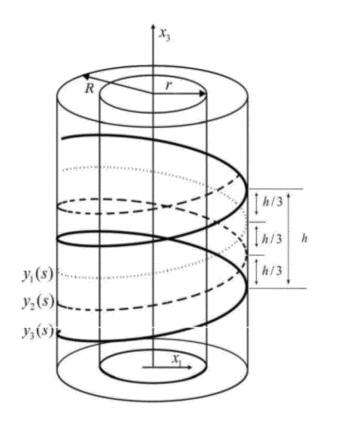
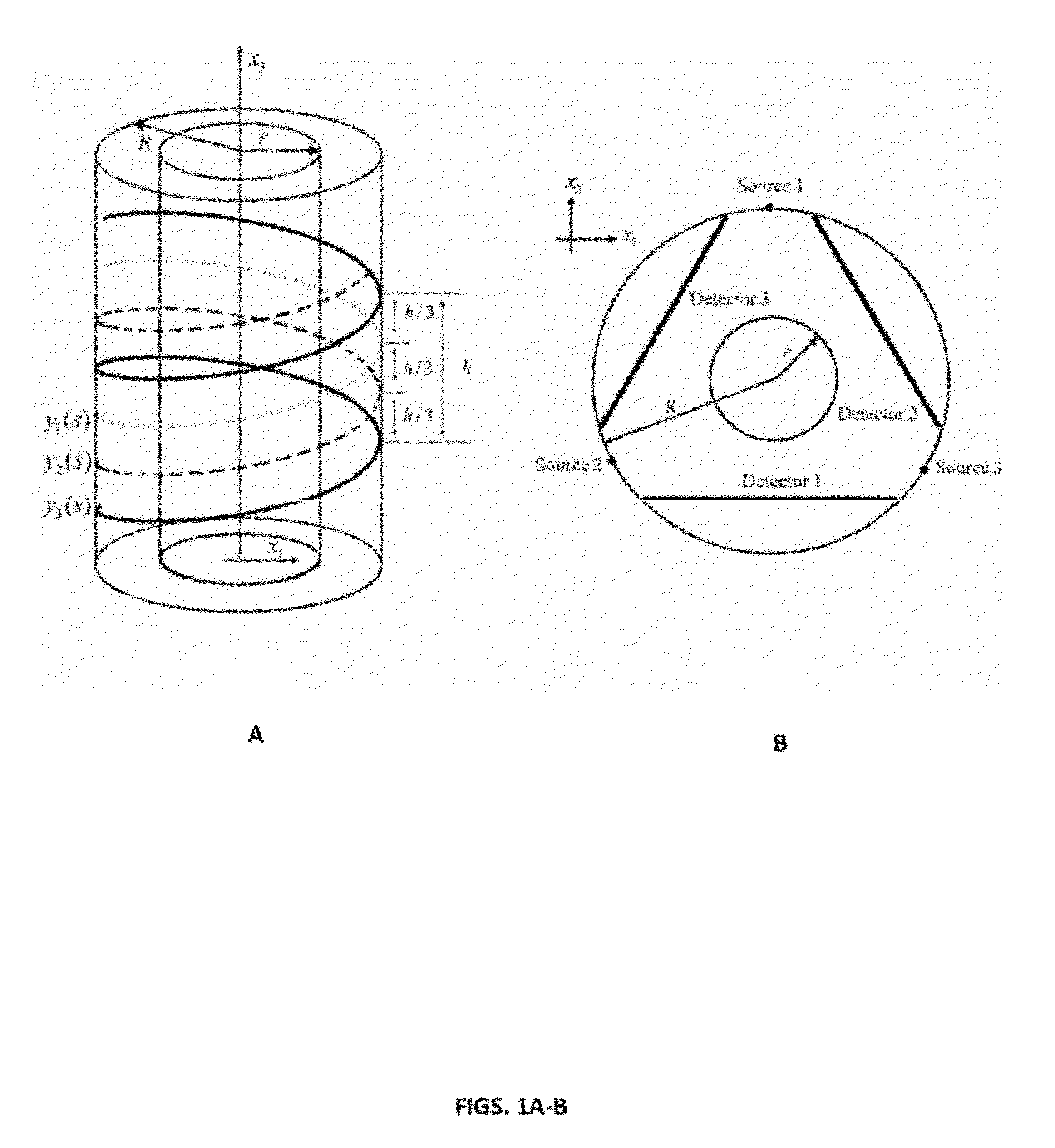
[0118]To verify and showcase the fast FBP algorithms of the present invention, numerical tests were performed using the Clock phantom. This phantom consists of ellipses, as parameterized in Table IV. In the simulations, the origin of the reconstruction coordinate system was set to the center of each phantom. The spherical phantom support was of 375 mm for the experiment. Three sources were arranged uniformly along a circle with their corresponding detectors on the opposite side. The source-detector distance was 1000 mm. Projections were generated from 1000 view angles while the sources and the detectors were constantly moved along three helixes in one turn. The helix was of 750 mm in radius and 100 mm in pitch. The detector plane consisted of 1300×200 detection elements of 1.0×1.0 mm2.

TABLE IVParameters of the Clock PhantomNo.xcyczcabcθρ100011101200.800.10.10.10130.40.690.010.10.10.10140.690.40.020.10.10.10150.800.030.10.10.10160.69−0.40.040.10.10.10170.4−0.690.050.10.10.10180−0.80....

example 2

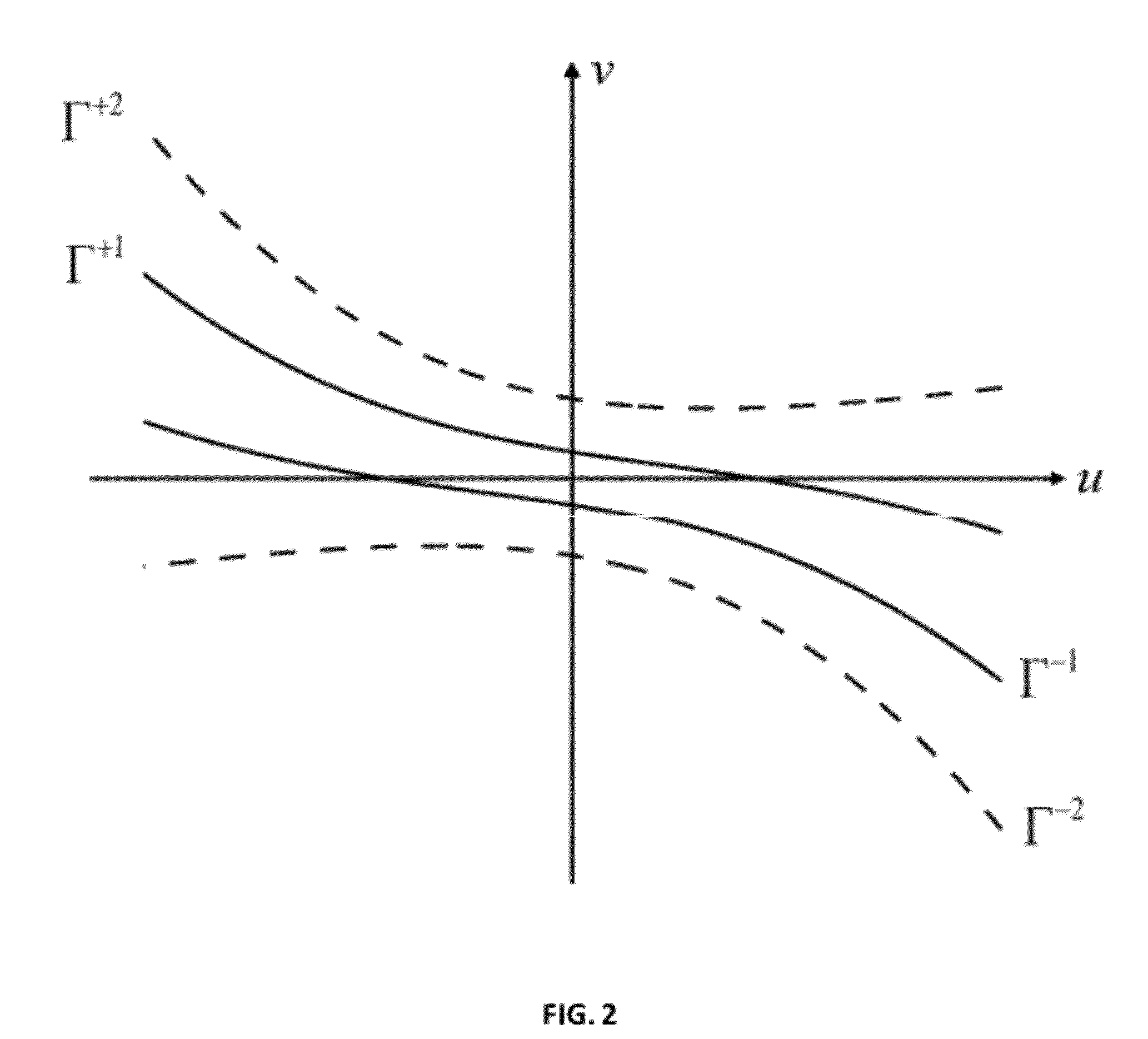
[0120]Auxiliary Lemmas were used as described below. A point was fixed at x∈Ω and its three associated inter-PI lines were found as shown in FIG. 3. Then, a source position was selected as s∈(sj3,sje), j∈{1,2,3} and how the inter-PI lines project onto the corresponding detector plane was determined. For simplicity, in this disclosure the projection of yi(s), j∈{1,2,3} on a detector plane is denoted by Ŝj.

[0121]Lemma 1. On a detector plane, the slopes of the projected inter-PI lines ŜjsŜjmod3+1e and Ŝ(j+1)mod3+1s Ŝje are always positive, and that of the inter-PI line Ŝjmod3+1sŜ(j+1)mod3+1e, j∈{1,2,3} is always negative.

[0122]Proof of Lemma 1. Without loss of generality or wishing to be limited by theory, the source position was selected to be y1(s0), s0∈(s1s,s1e). By construction, ss2e−s1s1e−s3s3e−s2s>0. Hence, the projections of s1s, s3e, and s3s were always to the left of those of s2e, s2e, and s1e respectively (FIG. 18). When s∈(s1s, s1e) changed, the point {circumflex over (x)}, ...


PUM


Abstract

The present invention provides systems, methods, and devices for improved computed tomography (CT). More specifically, the present invention includes methods for improved cone-beam computed tomography (CBCT) resolution using improved filtered back projection (FBP) algorithms, which can be used for cardiac tomography and across othertomographic modalities. Embodiments provide methods, systems, and devices for reconstructing an image from projection data provided by a computed tomography scanner using the algorithms disclosed herein to generate an image with improved temporal resolution.

Description

CROSS-REFERENCE TO RELATED APPLICATIONS[0001]This application claims priority to and the benefit of the filing date of U.S. Provisional Application No. 61 / 225,708, filed Oct. 28, 2009, which is incorporated by reference herein in its entirety.STATEMENT OF GOVERNMENT INTEREST[0002]This invention was made under government support under grants EB002667, EB004287, and EB007288 awarded by the NIH / NIBIB. The United States government has certain rights in and to the invention.BACKGROUND OF THE INVENTION[0003]1. Field of the Invention[0004]The present invention provides systems, methods, and devices for improved computed tomography (CT). More specifically, the present invention includes methods for improved cone-beam computed tomography (CBCT) resolution using improved filtered back projection (FBP) algorithms, which can be used for cardiac tomography and across other tomographic modalities.[0005]2. Description of Related Art[0006]Cardiovascular diseases (CVDs) are pervasive (American Heart...

Claims


Application Information

Patent Timeline
IPC IPC(8): A61B6/03
CPCA61B6/027A61B6/032A61B6/4085A61B6/503A61B6/5205G06T11/006G06T2211/412G06T2211/416G06T2211/421A61B6/508
Inventor WANG, GEZHAO, JUNLU, YANGYU, HENGYONGKATSEVICH, ALEXANDER
Owner VIRGINIA TECH INTPROP INC
Why Eureka
Try Eureka