Electrical connecting system

Inactive Publication Date: 2012-02-16
ROBERT BOSCH GMBH
View PDF8 Cites 11 Cited by
  • Summary
  • Abstract
  • Description
  • Claims
  • Application Information

AI Technical Summary

Benefits of technology

[0008]In addition, according to the exemplary embodiments and/or exemplary methods of the present invention one alternative specific embodiment of an electrical connecting system has at least one linear connecting piece, in particular at least one flat pin, the connecting piece being connected in an electrically conductive manner to the circuit board, in particular with the aid of a wire, and a printed conductor being situated between the connecting piece and a spring clip. In contrast to the first embodiment variant, no one-piece U-shaped contact spring is provided, and the electrical connection between the circuit board and the connecting piece, which may be designed, for example, as a flat pin which is injected into the plastic housing or as a contact plate, is established inside the plastic housing of the electronic module, which may be with the aid of conventional bonding technology. This results, among other things, in reduced material usage compared to the U-shaped contact springs. In addition, the integration of the connecting pieces and the spring clips into existing standard shapes of plastic housings of electronic modules is simplified.
[0009]A further difference from the first embodiment variant is that the electrical contact occurs only on one side, between the associated printed conductor of the printed circuit and the associated connecting piece. The only function of the spring clip is to build up the punctiform contact pressure required for establishing a secure electrical connection. As a result, the spring clip in this embodiment variant may be made of an electrically conductive metallic material, or also of a plastic material or any given combination thereof. The spr

Problems solved by technology

In particular, ensuring a reliable electrical connection between an electronic module, for example a mechatronic module located in an oil pan for controlling a motor vehicle transmission, causes significant

Method used


Image

  • Electrical connecting system
  • Electrical connecting system
  • Electrical connecting system

Examples


first embodiment

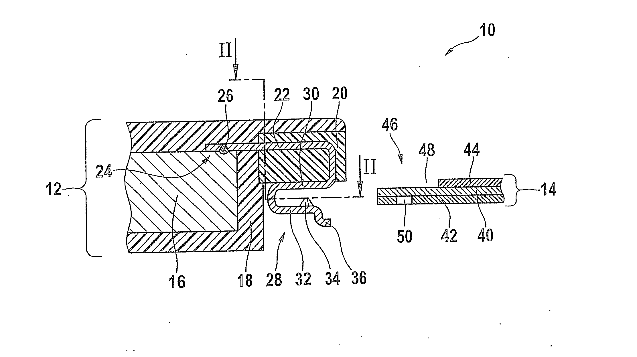
[0022]FIG. 1 shows a first embodiment variant of the connecting system according to the present invention.

[0023]A connecting system 10 includes an electronic module 12 and a flexible printed circuit 14. In the pulled-out position illustrated in FIG. 1, the electrical contact between printed circuit 14 and electronic module 12 is not yet established. Electronic module 12 includes, among other elements, a circuit board 16 which is enclosed by a plastic housing 18. Plastic housing 18 is formed from an electrically insulating thermoplastic or duroplastic plastic material. Multiple electronic and / or electromechanical components, not illustrated, are situated on circuit board 16. In addition, a contact spring strip 20 having at least one contact spring 22 is integrated into plastic housing 18. In general, contact spring strip 20 connects multiple contact springs which are uniformly spaced apart from one another in parallel. Contact spring strip 20 may be made of the same plastic material ...

embodiment 60

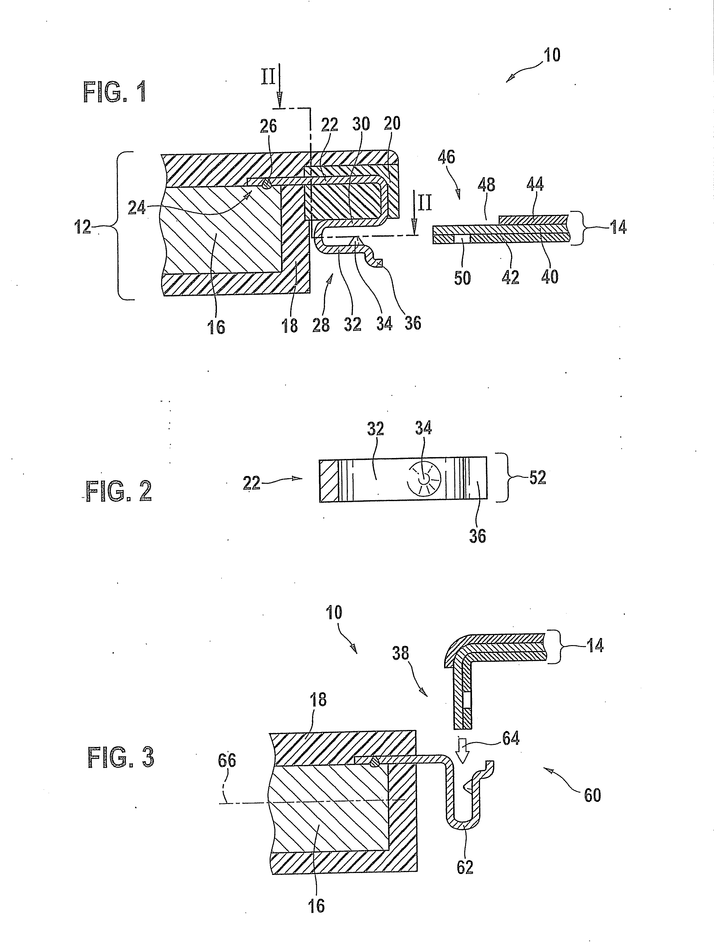
[0026]FIG. 3 illustrates one possible specific embodiment 60 of introducing the printed circuit at an angle greater than 0° with respect to electronic module 12 of connecting system 10.

[0027]In contrast to the specific embodiment according to FIG. 1, a contact spring 62 is integrated directly into the plastic housing of electronic module 12 and connected to circuit board 16 via a connecting point, not illustrated. A contact spring strip is not provided. In addition, flexible printed circuit 14, in a departure from FIG. 1, is introduced into contact spring 62 from above in the direction of white arrow 64, at an angle of up to 90° with respect to plane 66 of the circuit board. In addition, printed circuit 14 is bent by approximately 90° in connecting region 38 and led to contact spring 62. In other respects, the design of contact spring 60 is the same as for contact spring 22 described for FIG. 1, so that with regard to further design details, reference is made to the description of F...


PUM


Abstract

An electrical connecting system is described for contacting an electronic module with multiple printed conductors of a flexible printed circuit. The printed conductors are enclosed between a lower and an upper cover film, and the electronic module has at least one circuit board hich is embedded in a plastic housing. According to the invention, the electronic module has at least one contact spring. A first end section of the contact spring is connected in an electrically conductive manner to the circuit board via a connecting point, and a second end section of the contact spring has two legs which extend in a U shape, between which a printed conductor is situated. An electrical contact which is less susceptible to failure results on both sides between the contact spring and the printed conductor. Also described is an electrical connecting system in which the printed conductor is electrically contacted on one side, and instead of at least one one-piece contact spring, in each case a connecting piece and a spring clip are present. The electrical connecting systems allow an electrically reliable connection to be established which is also sufficiently capable of withstanding mechanical load, by simply inserting the printed circuits into the contact springs, or between the connecting pieces and the spring clips in the electronic modules.

Description

RELATED APPLICATION INFORMATION[0001]The present application claims priority to and the benefit of German patent application no. 10 2010 039 185.9, which was filed in Germany on Aug. 11, 2010, the disclosure of which is incorporated herein by reference.FIELD OF THE INVENTION[0002]The present invention relates to an eletrical connecting system.BACKGROUND INFORMATION[0003]Electronic system components are becoming increasingly important in motor vehicles. In particular, ensuring a reliable electrical connection between an electronic module, for example a mechatronic module located in an oil pan for controlling a motor vehicle transmission, causes significant problems for the sensors, the actuators, and other electronic modules.[0004]The electrical connection between a circuit board having electronic and electromechanical components which is usually located in the electronic module, and the external assembly and connection technology (ACT) is often established using bonding wires which ...

Claims


Application Information

Patent Timeline
IPC IPC(8): H01R12/79
CPCH01R4/02H01R12/71H01R12/79H01R12/778
Inventor LISKOW, UWE
Owner ROBERT BOSCH GMBH
Why Eureka
Try Eureka