
Method for simulating a blood flow

Active Publication Date: 2012-02-16
SIEMENS HEALTHCARE GMBH
View PDF2 Cites 42 Cited by
  • Summary
  • Abstract
  • Description
  • Claims
  • Application Information

AI Technical Summary

Benefits of technology

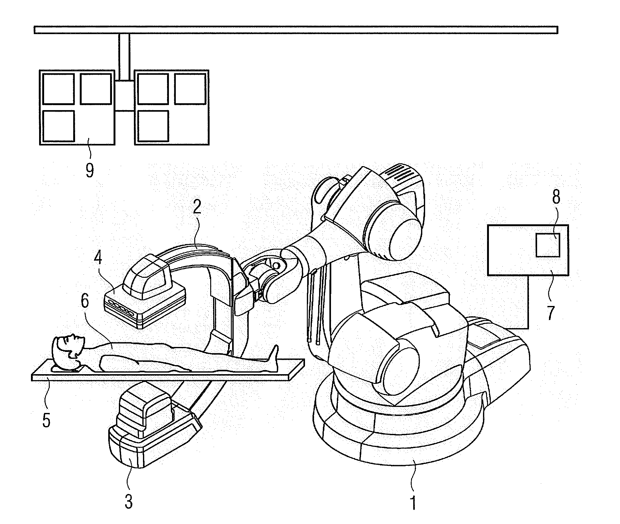
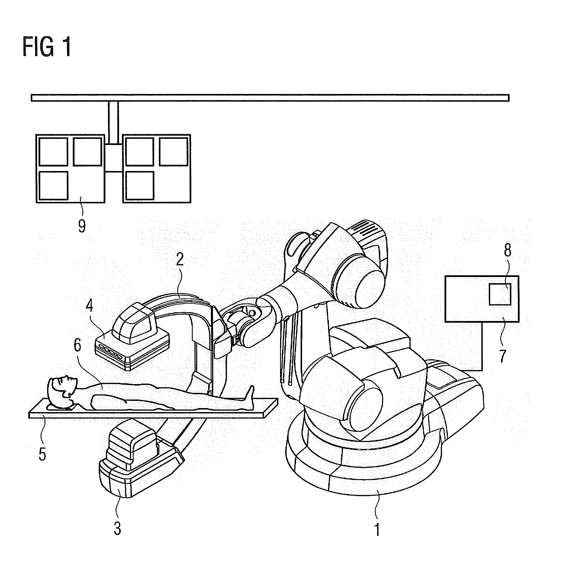
[0023]The object of the invention is to design a method for simulating a blood flow in a vascular segment of a patient during angiography examinations by a radiographic diagnostic device having a radiographic tube unit and a radiographic image detector, a patient support table and a system control unit, wherein a captured image of an examination region including the vascular segment is obtained, a 3D vascular model is determined from the captured image, a number of blood flow parameters are read in, and with the inclusion of these blood flow parameters the blood flow in the 3D vascular model is. The method enables the CFD simulation results to be validated for the individual patient, or any deviations to be quantitatively determined and used iteratively to improve the CFD simulation.
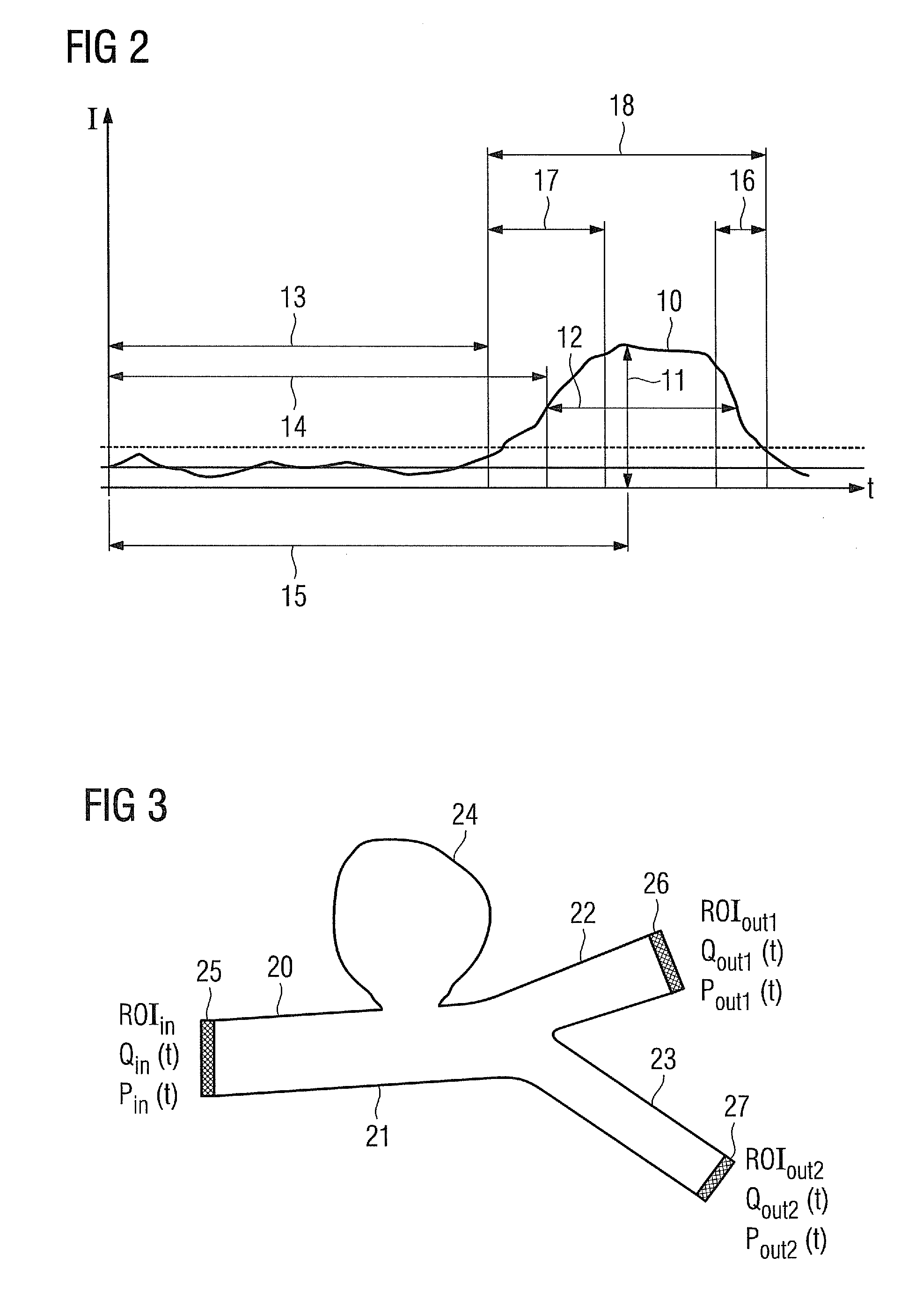
[0055]It has proved to be advantageous if the pressure difference between inflow region and outflow regions, the flow rate and / or the blood volume are selected as a basic condition as inflow and outflow values of the blood, changing over time.

Problems solved by technology

A major restriction is that in this specific application on humans not all basic conditions necessary for the simulation are sufficiently precisely known on an individual patient basis.
Hence it is difficult to validate the method and in the past this has not been done.
This means that the resulting flow results for the individual patient may be incorrect.
Hence it is difficult to validate the method.
The MR measurement itself is however imprecise because of the limited resolution and requires a considerable investment in time.
Moreover this examination is virtually never performed on patients.
However, neither method is suitable for validating the CFD measurement for the individual patient.

Method used


Image

  • Method for simulating a blood flow
  • Method for simulating a blood flow
  • Method for simulating a blood flow

Examples


Embodiment Construction

[0062]In the inventive method, apparatus and workflow a degree of correspondence between a virtual angiography from a CFD simulation and a real angiography scene is determined and this degree of correspondence is used to purposefully and iteratively optimize the CFD simulation.

[0063]This degree of correspondence is based on the comparison between a virtual angiography and a real angiography from identical angulation and adjusted recording geometry of the individual patient. The inventive determination of the degree of correspondence in 2-D is an alternative approach to Sun et al. [4].

[0064]Output data for this degree of correspondence is dynamic angiography scenes, which show the diffusion or passage of the contrast agent through the corresponding vascular system. The virtual dynamic angiography S* (the values indicated by * always relate in the following to the data derived from the virtual angiography) is obtained by means of CFD simulation. The time intensity curves TICi, j and T...


PUM


Abstract

A method for simulating a blood flow in a vascular segment of a patient is proposed. A 3D image dataset of an examination region is recorded by a radiographic diagnostic device for generating a 3D vascular model. Contrast agent propagation in the examination region is captured by a dynamic 2D angiography method for generating a real 2D angiography recording. A CFD simulation of the blood flow is performed in the 3D vascular model based on a blood flow parameter for generating a virtual 2D angiography recording. A degree of correspondence between the real and the virtual 2D angiography recordings is determined from identical angulation and adjusted recording geometry of the patient and compared with predefinable tolerance values. The CFD simulation is iteratively optimized while changing the blood flow parameter as a function of the comparison. The degree of correspondence is outputted when the optimum CFD simulation is achieved.

Description

CROSS REFERENCE TO RELATED APPLICATIONS[0001]This application claims priority of German application No. 10 2010 039 312.6 filed Aug. 13, 2010, which is incorporated by reference herein in its entirety.FIELD OF THE INVENTION[0002]The invention relates to a method for simulating a blood flow in a vascular segment of a patient during angiography examinations.BACKGROUND OF THE INVENTION[0003]“Computational Fluid Dynamics”, also known as CFD for short, is a method for simulating the blood flow in a vascular section or vascular segment of a blood vessel which contains a pathological, i.e. a morbid change. Such a pathological change in the vascular section exists for example in the form of an aneurysm, i.e. a morbid, locally delimited, frequently bag-like enlargement. An aneurysm can occur in particular in a blood vessel in the region of the brain or of the heart; however, the occurrence of an aneurysm is generally not restricted to a specific region of the body. The clinical significance ...

Claims


Application Information

Patent Timeline
IPC IPC(8): A61B6/00G06G7/60G06G7/57
CPCA61B6/4441A61B6/481A61B6/4458A61B6/507A61B6/504
Inventor REDEL, THOMAS
Owner SIEMENS HEALTHCARE GMBH
Learn More