
Method for selectively performing local and radial peripheral stimulation

a peripheral stimulation and selective technology, applied in the field of tissue stimulation systems, can solve the problems of difficult selective stimulation of peripheral nerve tissue, still remain issues, etc., and achieve the effect of reducing or eliminating pain

Inactive Publication Date: 2012-02-16
BOSTON SCI NEUROMODULATION CORP
View PDF2 Cites 42 Cited by
  • Summary
  • Abstract
  • Description
  • Claims
  • Application Information

AI Technical Summary

Benefits of technology

[0011]In accordance with another aspect of the present inventions, a method of providing therapy (e.g., a reduction in or elimination of pain) to a patient is provided. The method comprises initially conveying pulsed electrical current at a pulse amplitude and a pulse width into a peripheral tissue region of the patient, whereby one of a nerve ending is stimulated to create a side effect local to the peripheral neural tissue region and a neural axon is stimulated to create a side effect remote from the peripheral neural tissue region. The method further comprises adjusting the pulse width, and subsequently conveying pulsed electrical current at the adjusted pulse width into the peripheral tissue region of the patient, whereby only one of the other of the nerve ending is stimulated to create a therapeutic effect local to the peripheral neural tissue region and the neural axon is stimulated to create a therapeutic effect remote from the peripheral neural tissue region. In one method, both the initially and subsequently conveyed pulsed electrical current have the same pulse amplitude. Another method further comprises adjusting the pulse amplitude, wherein the pulsed electrical current is subsequently conveyed at the adjusted pulse amplitude into the peripheral region of the patient.

Problems solved by technology

While PS has been generally useful in treating patients, there still remain issues.
As such, it is often difficult to selectively perform PNFS and PNS.

Method used


Image

  • Method for selectively performing local and radial peripheral stimulation
  • Method for selectively performing local and radial peripheral stimulation
  • Method for selectively performing local and radial peripheral stimulation

Examples


Embodiment Construction

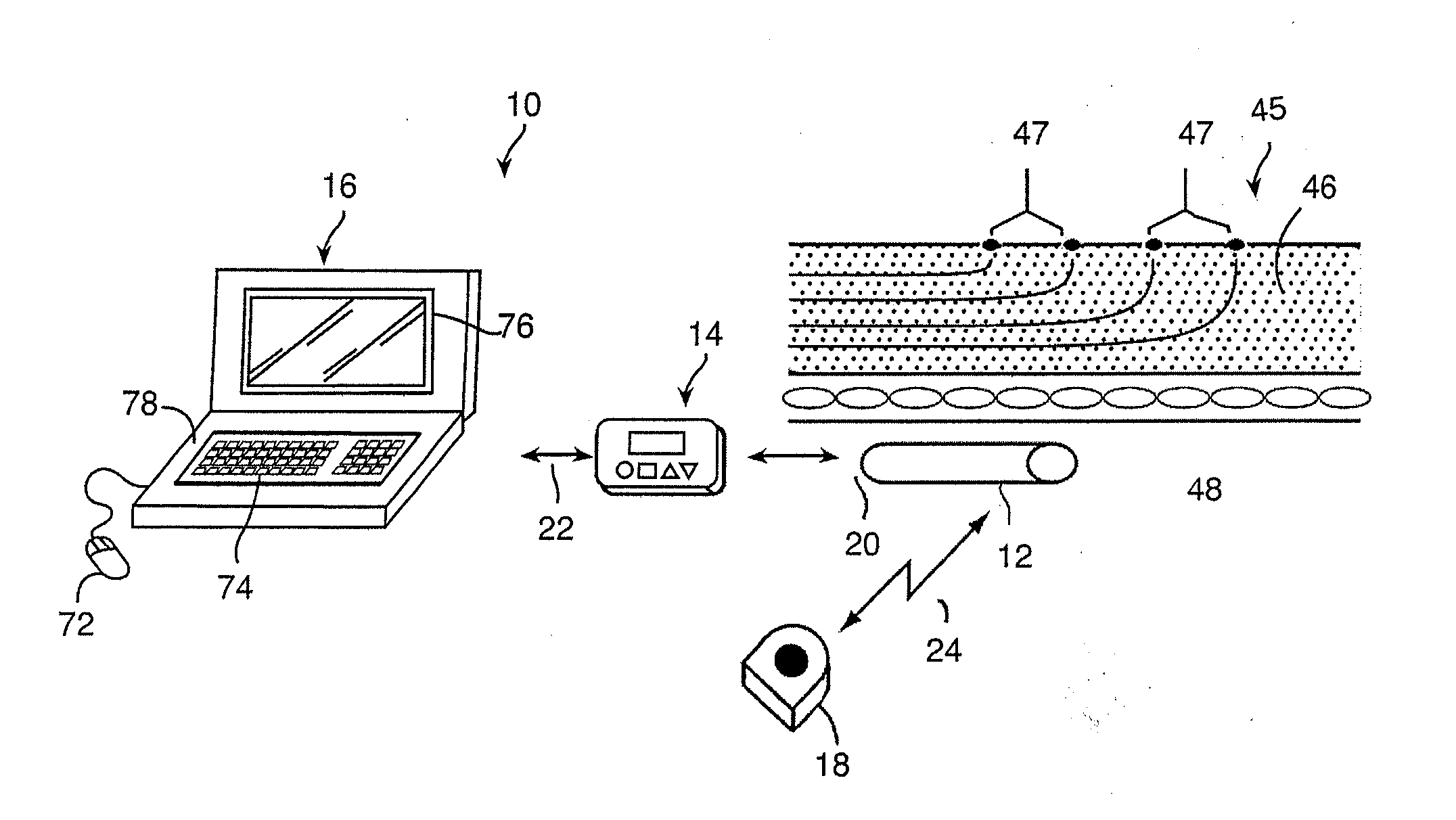
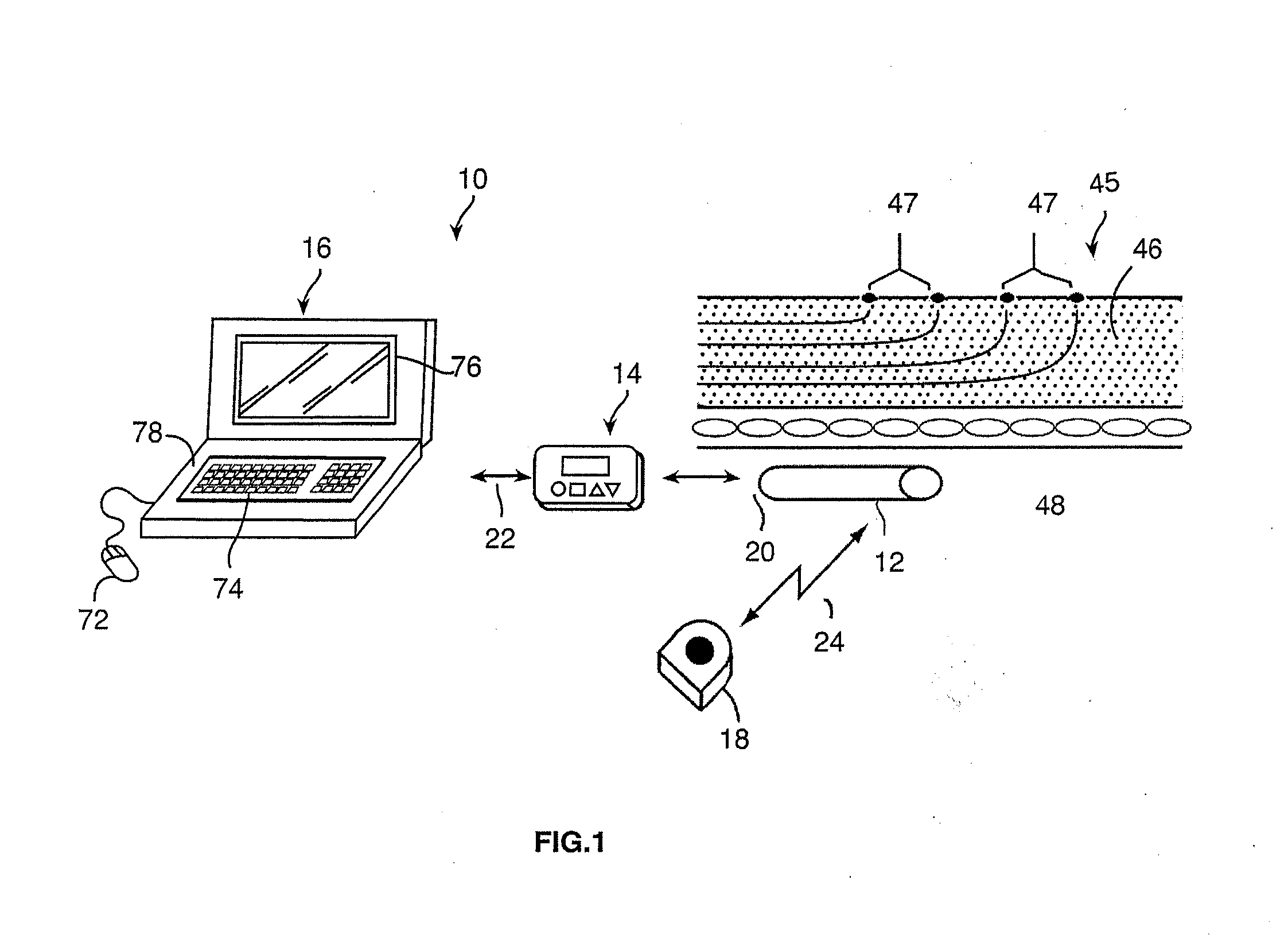
[0026]Turning first to FIG. 1, an exemplary neurostimulation system 10 is used to selectively perform Peripheral Nerve Field Stimulation (PNFS) and Peripheral Nerve Stimulation (PNS). The system 10 generally includes a neurostimulator in the form of a microstimulator 12, external control devices, and in particular a handheld remote controller (RC) 14 and a clinician's programmer (CP) 16, and an external charger 18.

[0027]The microstimulator 12 includes pulse generation circuitry that delivers electrical stimulation energy in the form of a pulsed electrical waveform (i.e., a temporal series of electrical pulses) to tissue in which the microstimulator 12 is implanted in accordance with a set of stimulation parameters. As shown in FIG. 1, the microstimulator 12 is subcutaneously implanted within a peripheral region 45 (e.g., an arm, leg, lower back, neck, etc.) of a patient using suitable means, such as a needle. The preferred placement of the microstimulator 12 is just below the cutane...


PUM


Abstract

A control system for use with a neurostimulator comprises a user interface for receiving an input from a user and a controller. The user interface has a first control and a second control. The controller is configured for, in response to actuating the first control, operating the neurostimulation control system in a PNFS programming mode, and for, in response to actuating the second control, operating the neurostimulation control system in a PNS programming mode. A method of providing therapy to a patient comprises initially conveying pulsed electrical current at a pulse width into a peripheral tissue region of the patient to create a side effect via stimulation of one of a nerve ending and neural axon, and subsequently conveying pulsed electrical current at an adjusted pulse width into the peripheral tissue region to create a therapeutic effect via stimulation of the other one of the nerve ending and neural axon.

Description

RELATED APPLICATION DATA[0001]The present application claims the benefit under 35 U.S.C. §119 to U.S. provisional patent application Ser. No. 61 / 373,692, filed Aug. 13, 2010. The foregoing application is hereby incorporated by reference into the present application in its entirety.FIELD OF THE INVENTION[0002]The present invention relates to tissue stimulation systems, and more particularly, to a system and method for peripherally stimulating nerve tissue.BACKGROUND OF THE INVENTION[0003]Implantable neurostimulation systems have proven therapeutic in a wide variety of diseases and disorders. In recent investigations, Peripheral Stimulation (PS) (i.e., stimulation of nerve tissue outside of the spinal cord and brain), which includes Peripheral Nerve Field Stimulation (PNFS) techniques that stimulate nerve tissue directly at the symptomatic site of the disease or disorder (e.g., at the source of pain), and Peripheral Nerve Stimulation (PNS) techniques that directly stimulate bundles of...

Claims


Application Information

Patent Timeline
Patent Type & Authority Applications(United States)
IPC IPC(8): A61N1/34A61N1/36A61N1/08
CPCA61N1/36071A61N1/36175G06F19/3406A61N1/37247A61N1/37205G16H40/63
Inventor LEE, DONGCHUL
Owner BOSTON SCI NEUROMODULATION CORP
Learn More