System for the central control of operational devices

a technology of operational devices and control systems, applied in the direction of temperatue control, instruments, structural/machine measurement, etc., can solve the problems of high cost, inability to take into account the overall heat of the house, and inability to meet the needs of users, so as to avoid the effect of individual change of the operational state and strong fluctuations in the operational state of the user

Inactive Publication Date: 2012-02-16
WILMSEN GMBH & CO HANDELS
View PDF2 Cites 17 Cited by
  • Summary
  • Abstract
  • Description
  • Claims
  • Application Information

AI Technical Summary

Benefits of technology

[0007]It is therefore desirable to provide an improved system for controlling operational devices which resolves at least some of the aforementioned problems and leads to better energy efficiency.
[0010]Therefore, a control signal is pre-specified in order to always regulate an operational state of an operational device to an operational state setpoint value. Thus, inefficient, large operational state changes which can result from interventions by the user can be avoided, and more efficient use of energy can be achieved by central control of, for example, the apartment and building temperature.
[0015]Preferably, the at least one control unit is connected wirelessly to the at least two operational device controllers and the at least two sensors for communicating. Therefore, the position of the control unit in the building is also independent of internal building lines, and this greatly facilitates modification of an existing system and / or installation of a new system.
[0016]Furthermore, every operational device controller preferably has identification so that a control signal with corresponding identification can be assigned to an operational device controller. Individual communication with different operational device controllers is thus simplified, and fine-tuning of the operational state, for example in different spaces, is made possible.
[0018]In a further embodiment a method for the central control of operational devices, particularly for a plurality of buildings, is described. The method comprises the steps of receiving a signal transmitted from a central control unit with operational state setpoint value information with a control unit in a building, and receiving an operational state detection signal from at least one sensor which is representative of the operational state, such as a temperature, in a space. The method further comprises the steps of generating in the control unit a control signal on the basis of the signal transmitted by the central control unit and the operational state detection signal and transmitting the control signal to an operational device controller for controlling at least one operational device in the space. Therefore, the operational state in a space can be specified from a central point so that strong fluctuations in the operational state due to individual changing of the operational state by a user can be avoided.

Problems solved by technology

With such heating systems the overall heat of the house is generally not taken into account because users control the temperature of their apartments individually or possibly also do not control it in their absence.
However, fluctuating temperatures in buildings are not energy-efficient, i.e. by changing the temperature in a building more uniformly or by keeping it constant energy could be saved.
Moreover, heating bills for individual apartments are generally not produced dependently upon the prevailing temperature in the apartment, but upon the basis of units of heat consumed which are usually read more or less correctly directly from heating appliances, and this gives rise to high costs.
Timer switches and similar devices can be used here, but monitoring of such devices with sensors is not provided.
This can easily lead to there being good room illumination when the sun is shining, but the inhabitant forgetting to switch the lights off.
In business and office areas this problem is even greater because often the employees do not feel responsible for the energy costs and do not turn off the lights when they leave their place of work.

Method used


Image

  • System for the central control of operational devices
  • System for the central control of operational devices
  • System for the central control of operational devices

Examples


Embodiment Construction

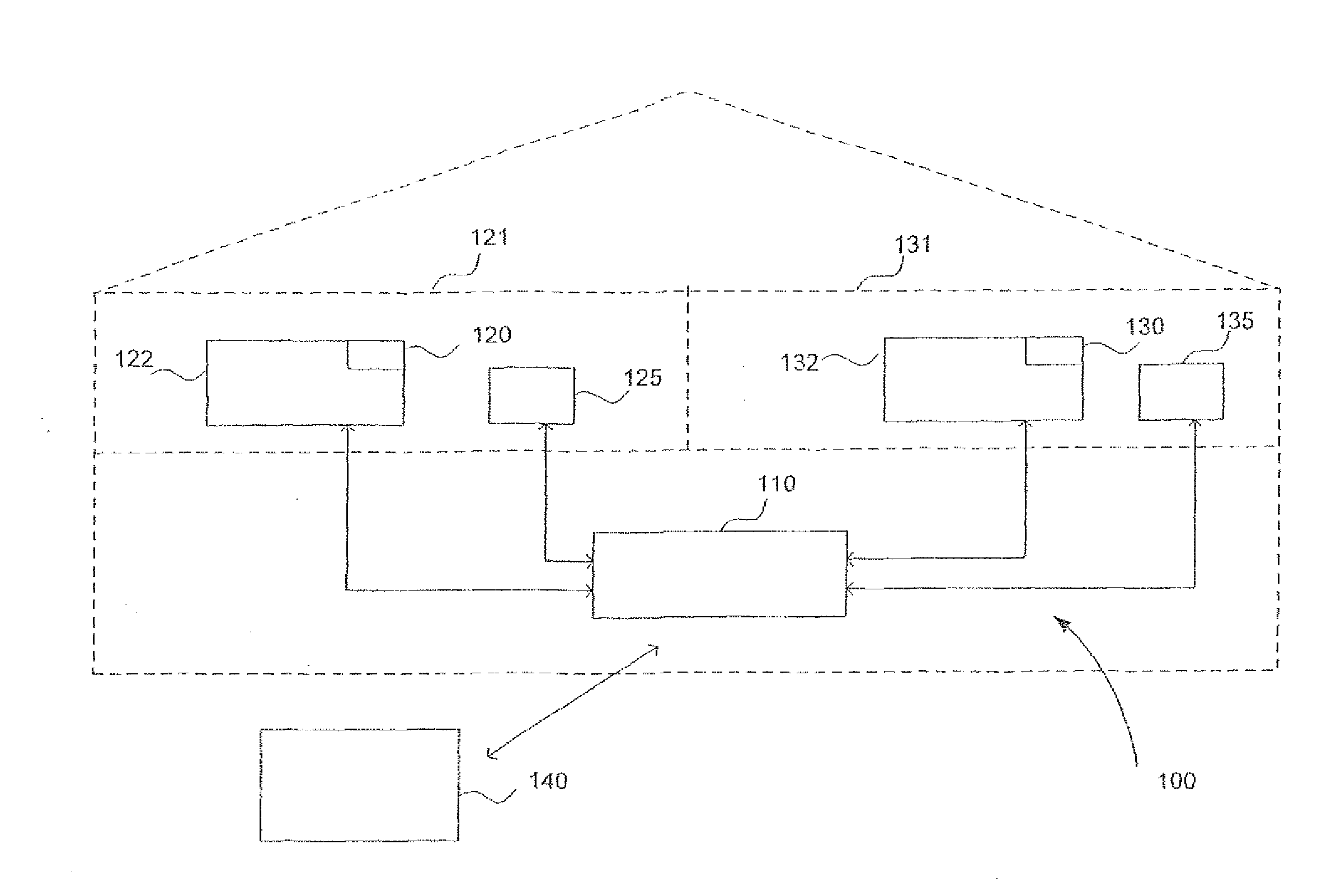
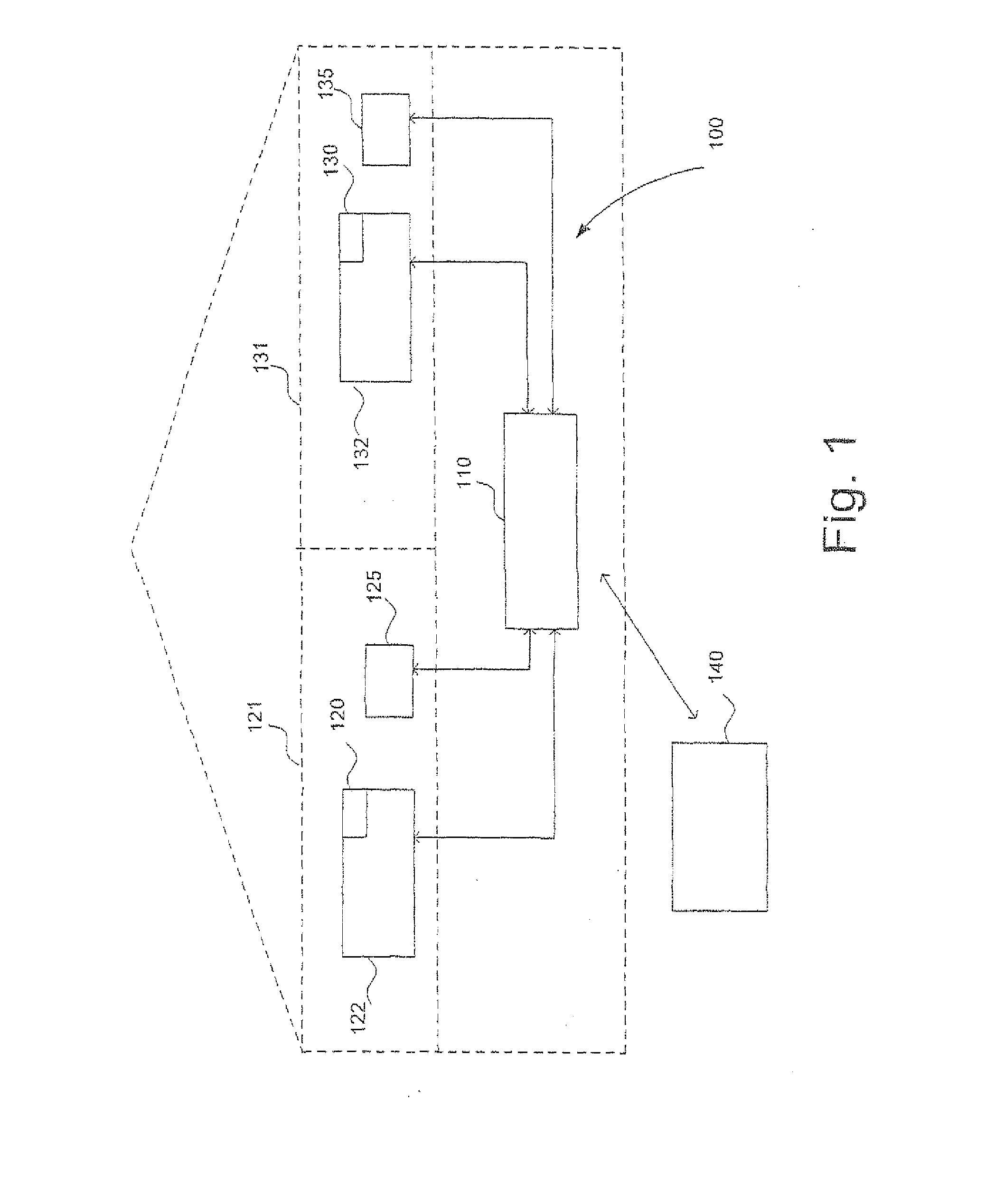
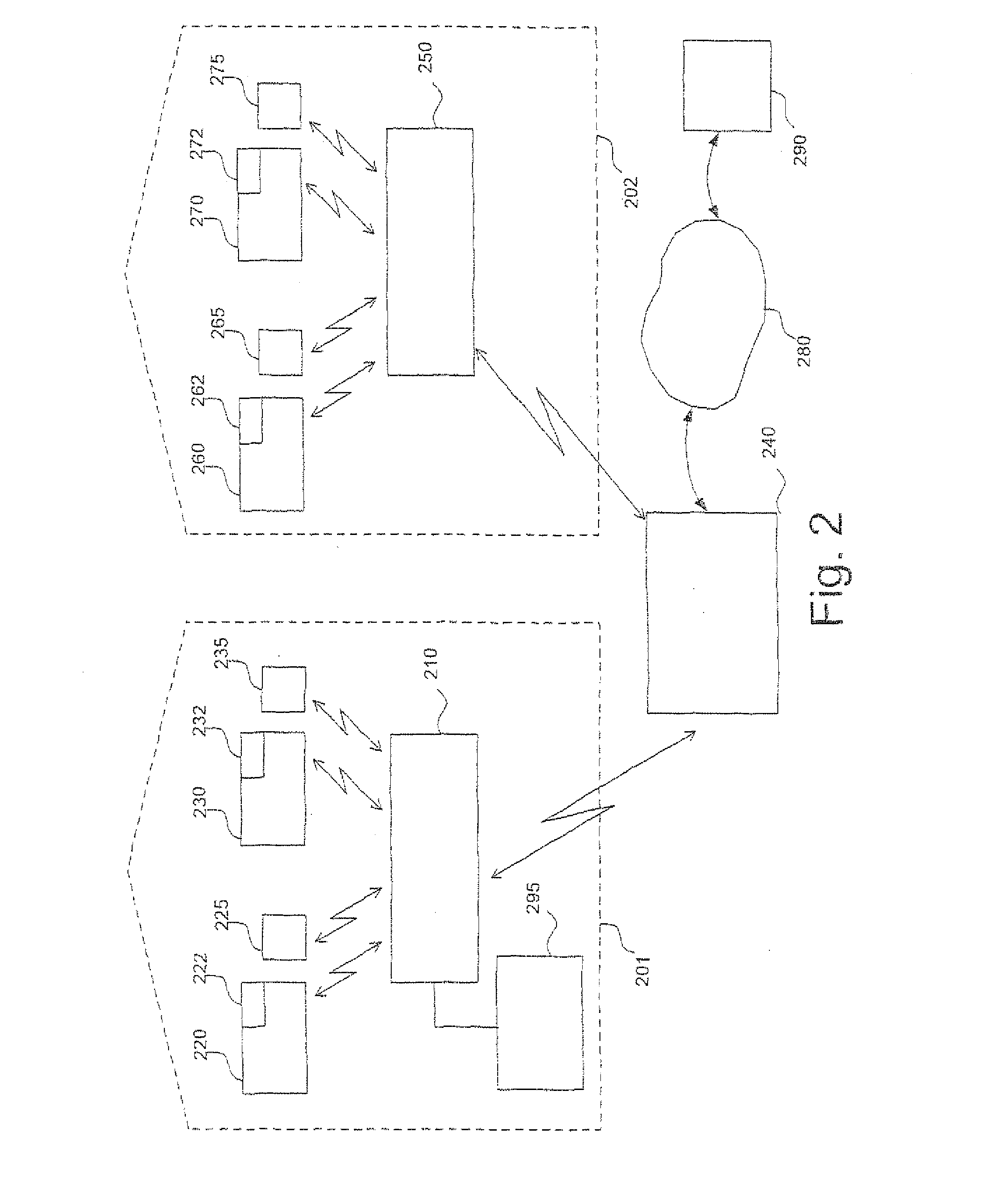
[0022]In the following, preferred embodiments of the present invention are described in detail with reference to the accompanying drawings. Here, in different drawings, the same or corresponding components are respectively identified with the same or similar reference numbers.

[0023]The preferred embodiments of the invention, which are described in detail below, are described in detail with reference to a system for the control of heating devices in rooms of buildings. It is noted, however, that the heating device can also be understood to be an air-conditioning system, i.e. for heating and for cooling. It is further noted that the heating device is only described representatively of other operational devices. A heating device can also be understood to be an air-conditioning system for heating and for cooling because the concept of an increase in temperature can also be applied immediately to a reduction in temperature. Different operational devices can be any type of electrical appl...


PUM


Abstract

The present invention describes a system for the central control of operational devices, and in particular an improved system for the central control of operational devices in a plurality of spaces or buildings which uses energy, for example heating energy, cooling energy or light energy, more efficiently. The system comprises at least two operational device controllers for controlling at least two operational devices and is designed to receive a control signal; at least two sensors for detecting the operational state in at least two spaces; at least one control unit in a building which is designed to receive an operational state-detection signal and for transmitting a control signal; and a central control unit which is communicatively connected to the at least one control unit for transmitting and receiving signals, wherein the control unit generates the control signal on the basis of operational state setpoint value information in a signal from the central control unit.

Description

TECHNICAL DOMAIN[0001]The present invention relates to a system for the central control of operational devices, and in particular a system for the central control of heating devices, cooling devices, lighting devices, etc. in a plurality of spaces or buildings, which can be controlled remotely from a central control unit.PRIOR ART[0002]A number of different control / regulating systems for operational devices are known. For example, in the simplest case heating appliances are equipped with a device for roughly controlling the temperature, such as a valve which when opened introduces hot water into the heating appliance, Furthermore, heating systems are known which make it possible for a temperature to be pre-specified for a space, the temperature of the space then being regulated to this value by the system.[0003]With such heating systems the overall heat of the house is generally not taken into account because users control the temperature of their apartments individually or possibly...

Claims


Application Information

Patent Timeline
Patent Type & Authority Applications(United States)
IPC IPC(8): G05D23/19
CPCG05D23/1934
Inventor WILMSEN, JORG
Owner WILMSEN GMBH & CO HANDELS
Why Eureka
Try Eureka