
Multi-Spar Port Box Joint

a multi-spar, port box technology, applied in the field of aircraft, can solve the problems of affecting the service life of various components in the aircraft, the opening may not provide the desired airflow over the horizontal stabilizer, and the complexity of the horizontal stabilizer may be present, so as to achieve the effect of increasing the load and increasing the load

Active Publication Date: 2012-02-23
THE BOEING CO
View PDF0 Cites 23 Cited by
  • Summary
  • Abstract
  • Description
  • Claims
  • Application Information

AI Technical Summary

Benefits of technology

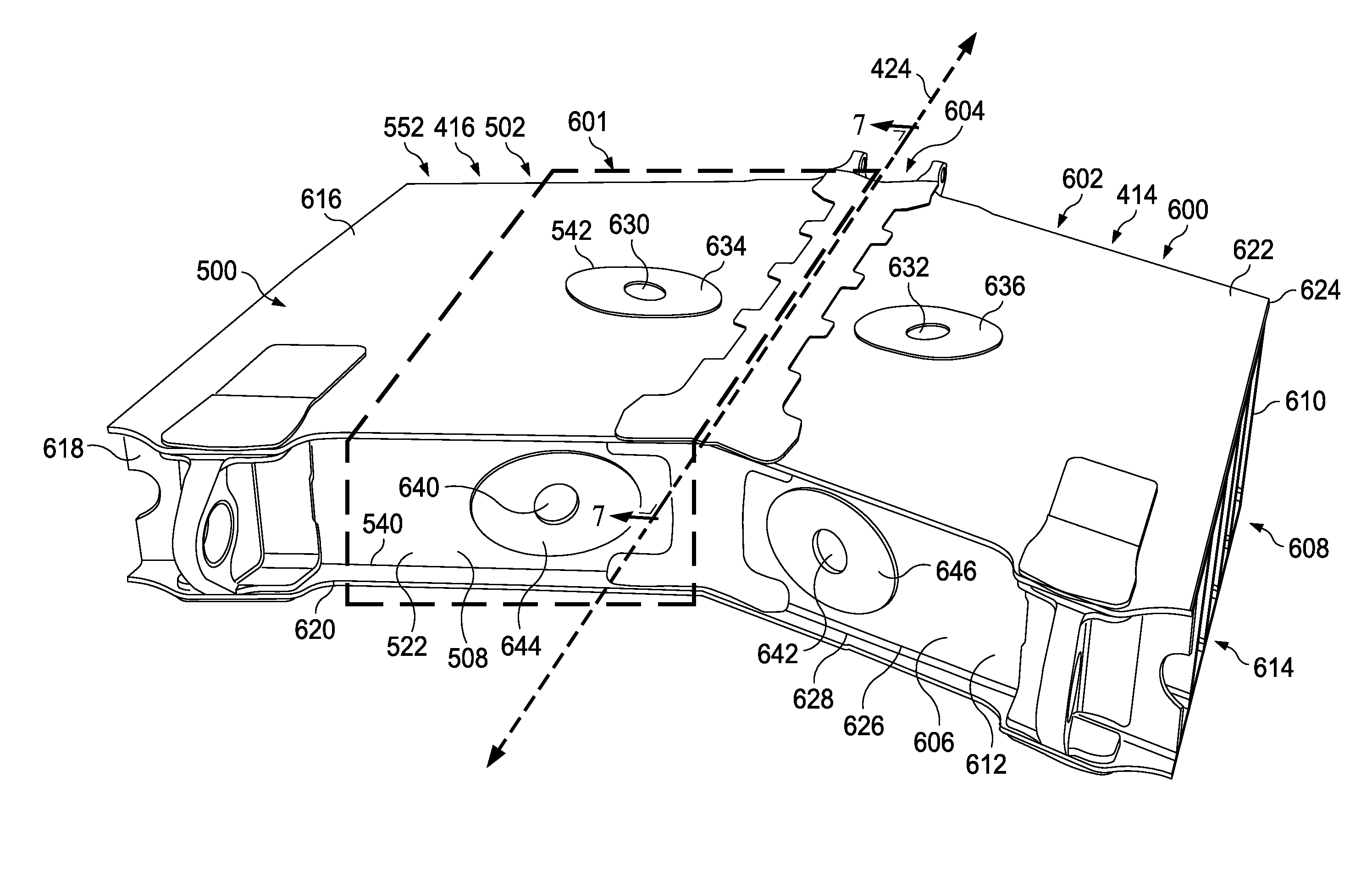
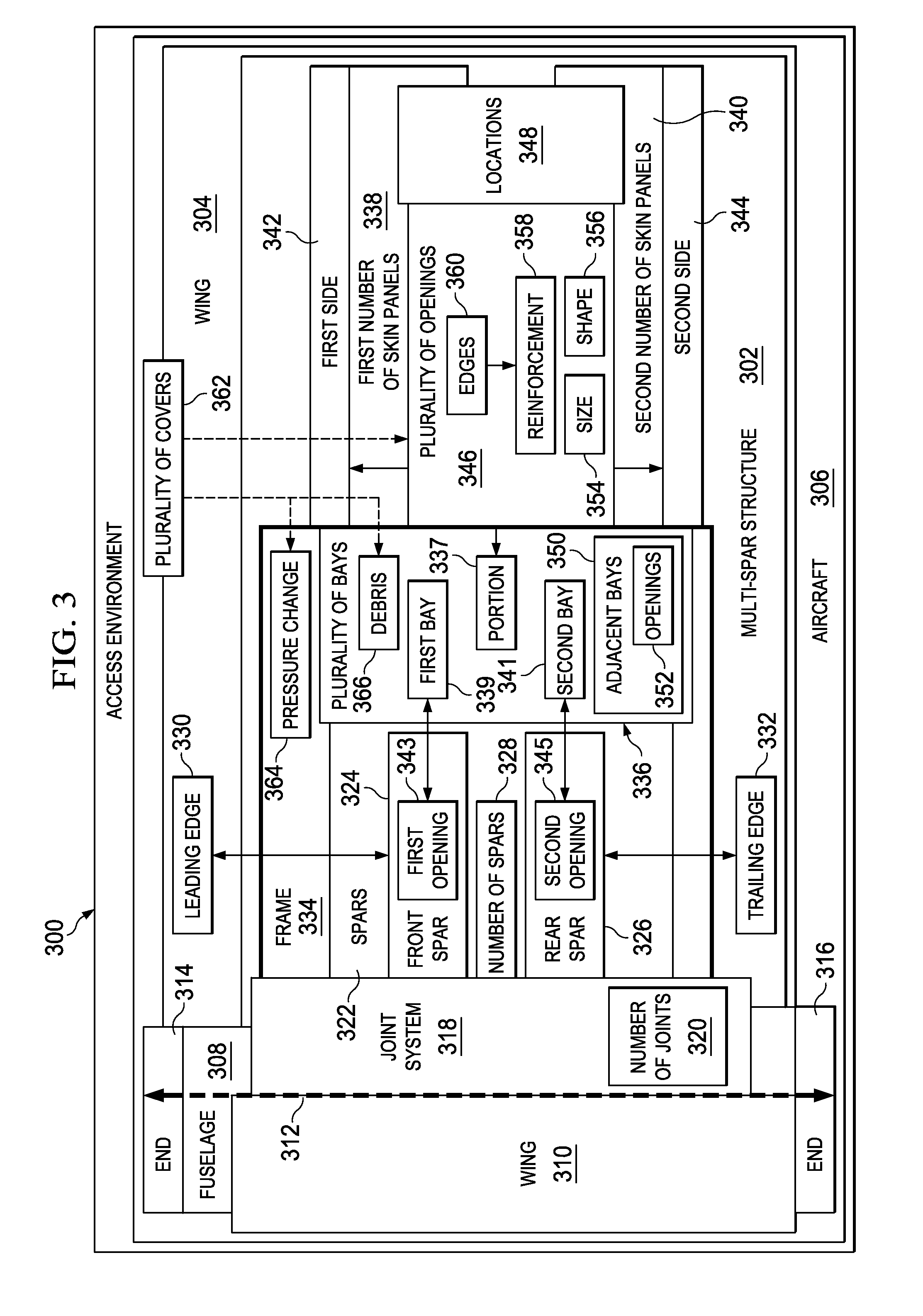
[0010]In another advantageous embodiment, a multi-spar wing structure for an aircraft may comprise a front spar, a rear spar, a number of spars located between the front spar and the rear spar in which the front spar, the rear spar, and the number of spars form a frame, a first number of skin panels on a first side of the frame, a second number of skin panels on a second side of the frame, a plurality of openings, a plurality of covers, and a fuselage of the aircraft. The front spar may have a first opening to a first bay in a plurality of bays. The rear spar may have a second opening to a second bay in the plurality of bays. The frame may have a plurality of bays. The frame may be a part of a wing of the aircraft and may comprise a box for the wing. An end of the frame may be configured to be attached to at least one of a fuselage of the aircraft and a corresponding frame for a second wing. The first side of the frame may be substantially opposite to the second side of the frame. The plurality of openings may be in the first number of skin panels on the first side and in the second number of skin panels on the second side. The plurality of openings may be in locations such that each bay in a portion of the plurality of bays has an opening and such that openings alternate between the first side and the second side between adjacent bays in the plurality of bays in a manner that avoids two adjacent bays having openings on a same side. The portion of the plurality of bays, the first bay, and the second bay may form the plurality of bays. The locations of the plurality of openings may be selected to provide access to a joint system to which the end of the frame is connected in which the joint system is located substantially at a centerline of the fuselage of an aircraft and to increase a load that can be applied to the first number of skin panels and the second number of skin panels. An edge of the opening in the plurality of openings may be reinforced. The plurality of openings may have a shape selected from one of a circle, an oval, and a race track. The plurality of covers may be configured to cover a first number of openings and a second number of openings in the plurality of openings. The plurality of covers may be configured to increase the load that may be supported by the first number of skin panels and the second number of skin panels when the plurality of covers is installed in the first number of openings and the second number of openings and to reduce at least one of a pressure change inside the frame during flight of the aircraft on which the frame is associated and debris entering the plurality of bays.

Problems solved by technology

Further, composite materials may provide longer service life for various components in an aircraft.
The openings may not provide desired airflow over the horizontal stabilizers.
As a result, a desired increase in complexity of the horizontal stabilizer may be present.
These designs for the access panels may increase the weight of the aircraft.
As a result, some gains in weight savings that may occur through the use of composite materials may be lost through the use of access panels.

Method used


Image

  • Multi-Spar Port Box Joint
  • Multi-Spar Port Box Joint
  • Multi-Spar Port Box Joint

Examples


Embodiment Construction

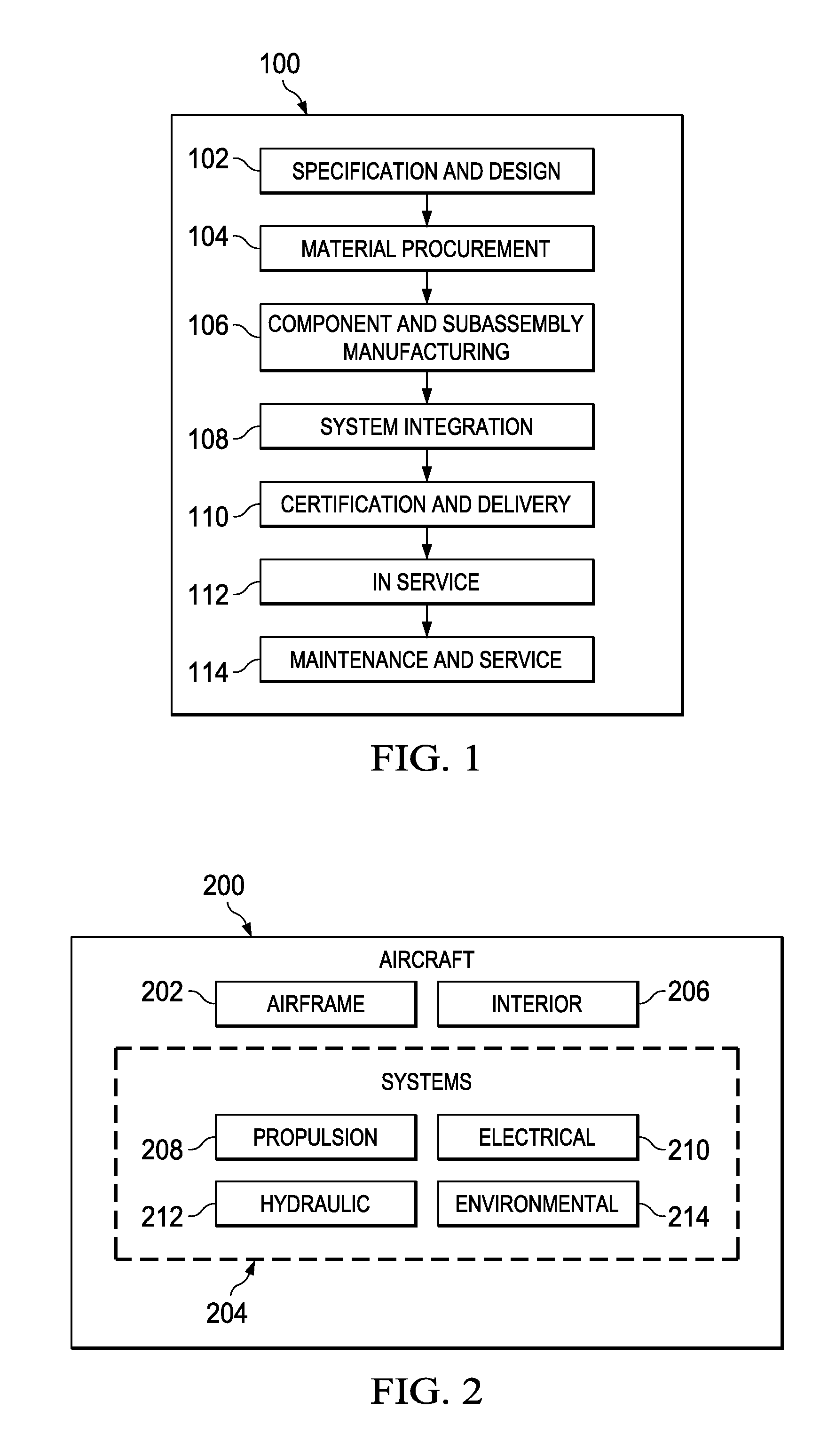
[0030]Referring more particularly to the drawings, embodiments of the disclosure may be described in the context of aircraft manufacturing and service method 100 as shown in FIG. 1 and aircraft 200 as shown in FIG. 2. Turning first to FIG. 1, an illustration of an aircraft manufacturing and service method is depicted in accordance with an advantageous embodiment. During pre-production, aircraft manufacturing and service method 100 may include specification and design 102 of aircraft 200 in FIG. 2 and material procurement 104.

[0031]During production, component and subassembly manufacturing 106 and system integration 108 of aircraft 200 in FIG. 2 may take place. Thereafter, aircraft 200 in FIG. 2 may go through certification and delivery 110 in order to be placed in service 112. While in service 112 by a customer, aircraft 200 in FIG. 2 may be scheduled for routine maintenance and service 114, which may include modification, reconfiguration, refurbishment, and other maintenance or ser...


PUM

PropertyMeasurementUnit
diameteraaaaaaaaaa
diameteraaaaaaaaaa
sizeaaaaaaaaaa

Abstract

A method for connecting a wing. A frame for a wing may be positioned relative to a fuselage of an aircraft. The frame may have bays and comprise a front spar, a rear spar, and a number of spars located between the front and rear spars. A first number of skin panels may be on a first side of the frame, and a second number of skin panels may be on a second side of the frame. The first side may be opposite to the second side. Openings may be in the first and second numbers of skin panels. The openings may be in locations such that each bay has an opening and such that the openings may alternate between the first side and the second side between adjacent bays in the bays. The frame may be attached to the fuselage using the openings to access an interior of the frame.

Description

BACKGROUND INFORMATION[0001]1. Field[0002]The present disclosure relates generally to aircraft and, in particular, to manufacturing aircraft. Still more particularly, the present disclosure relates to a method and apparatus for providing access to a joint in an aircraft.[0003]2. Background[0004]Aircraft are being designed and manufactured with greater and greater percentages of composite materials. Some aircraft may have more than 50 percent of their primary structure made from composite materials. Composite materials may be used in aircraft to decrease the weight of the aircraft. This decreased weight may improve payload capacities and fuel efficiencies. Further, composite materials may provide longer service life for various components in an aircraft.[0005]For example, horizontal stabilizers may be formed from composite materials. The spars, skin panels, and other components in a horizontal stabilizer may be formed from composite materials. When joining two horizontal stabilizers ...

Claims


Application Information

Patent Timeline
Patent Type & Authority Applications(United States)
IPC IPC(8): B64C3/18B21D39/03
CPCB64C1/26Y10T29/49826B64C3/26
Inventor CAMPANA, JOSEPH H.
Owner THE BOEING CO
Learn More