
LED circuits and assemblies

a technology of led circuits and assemblies, applied in the direction of lighting apparatus, electroluminescent light sources, light sources, etc., can solve the problems of imbalanced bridge effect and inability to meet voltage requirements, and achieve the effect of reducing objectionable flicker, improving design ease, and reducing objectionable flicker

Inactive Publication Date: 2012-02-23
LYNK LABS INC
View PDF2 Cites 39 Cited by
  • Summary
  • Abstract
  • Description
  • Claims
  • Application Information

AI Technical Summary

Benefits of technology

[0003]While not intending to limit the scope of the claims or disclosure, in brief summary, the present disclosure and claims are directed to providing improved ease of designing and building lighting fixtures using AC-driven LEDs. Disclosed and claimed are LED circuits having scalable circuit configurations and LED package assembly configurations which can be used in an AC-drive platform to more easily match the voltage requirements of the lighting fixture(s) or systems in which the LED's are desired. Circuits and LED package assemblies are claimed and disclosed which reduce objectionable flicker produced from AC-driven LEDs and to produce more light per component. Packaged LED's are provided for lighting design according to the invention which address flicker at low frequencies (e.g. 50 / 60 Hz) while being scalable as desired for a particular lighting goal without resort to designing individual assemblies at the semiconductor die level. Circuits are also disclosed and claimed which provide for some of the LEDs in a circuit to be on during both positive and negative phases of an AC source, to among other things, address flicker. Also, circuits are claimed and disclosed where a basic circuit design provides a voltage and current performance whereby scalability or matching a particular voltage requirement is achieved by configuring LEDs in the basic design and / or by joining one or more of the basic circuits together in series or basic to achieve the design requirement.
[0005]An AC LED bridge is an LED topology where the self rectifying property of anti basic LED strings is used to drive a set of ‘bridge’ LEDs with rectified current. An imbalanced bridge is the general implementation of this topology where one side of the input to the bridge has a different number of LEDs in series than the other side. A balanced bridge is a particular implementation of this topology where the input and output sides have equal numbers of LEDs in series. When used in a specific voltage drive regime, such as 12V AC, the advantage of an imbalanced bridge topology is that it can be constructed for example with standard GaN die so that the forward combined voltage of the die in one phase cycle is closely matched to the native supply voltage while the reverse voltage applied to the diodes in the opposing phase is kept to an acceptable level blow the reverse breakdown voltage of the die.

Problems solved by technology

It is important to note that according to an embodiment and aspect of the invention that circuits disclosed and claimed herein, result in an antibasic relationship of certain LEDs and further resulting in an imbalanced bridge effect in operation.
An imbalanced bridge is the general implementation of this topology where one side of the input to the bridge has a different number of LEDs in series than the other side.

Method used


Image

  • LED circuits and assemblies
  • LED circuits and assemblies
  • LED circuits and assemblies

Examples


Embodiment Construction

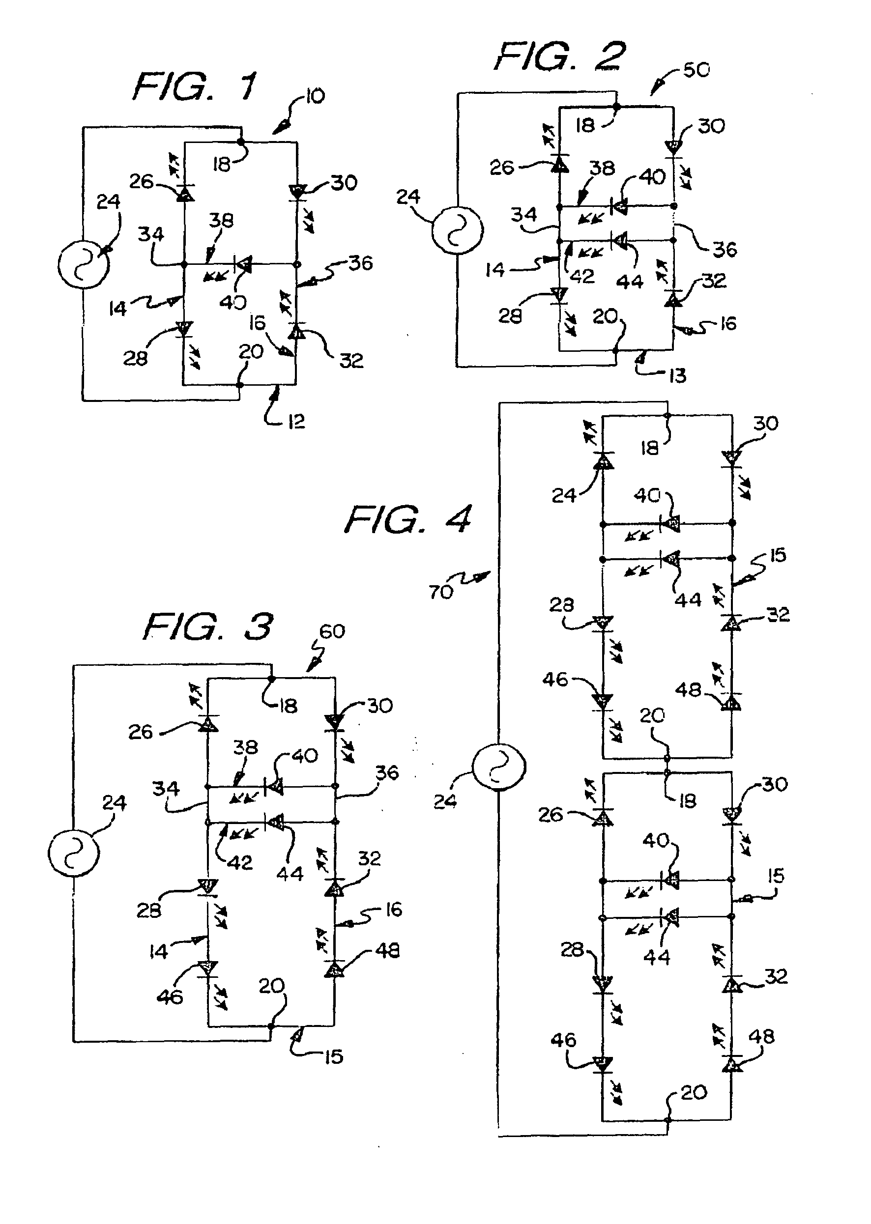
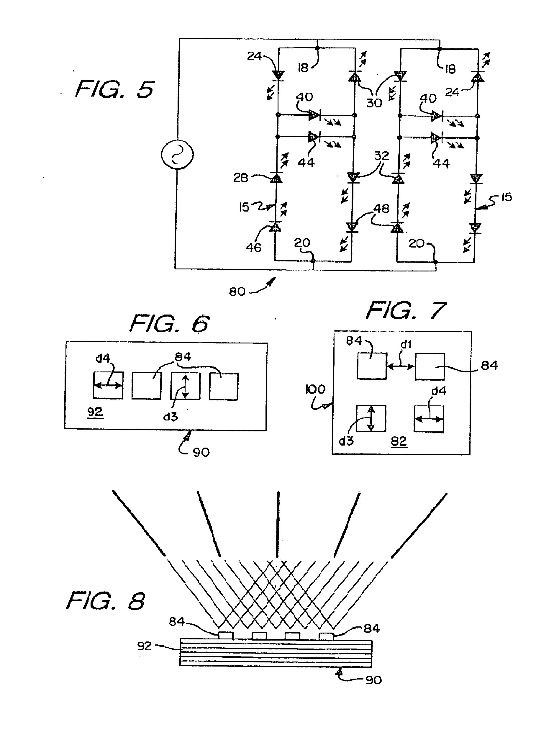
[0021]While this invention is susceptible to embodiments in many different forms, there are shown in the drawings and will herein be described in detail, preferred embodiments of the invention with the understanding that the present disclosures are to be considered as exemplifications of the principles of the invention and are not intended to limit the broad aspects of the invention to the embodiments illustrated. Like components in the various FIGS. will be given like reference numbers.

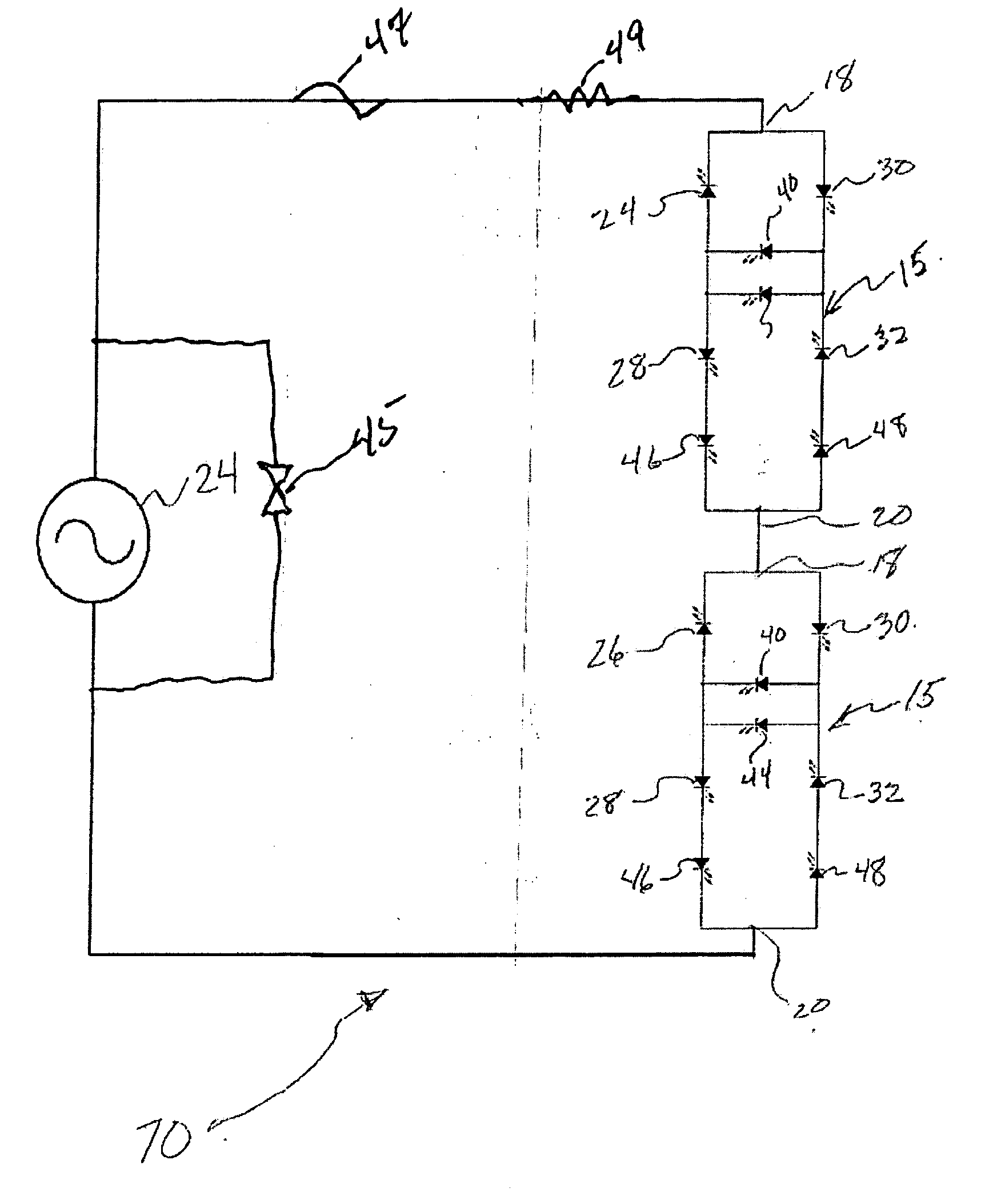
[0022]FIG. 1 discloses an AC-driven LED circuit 10 including a first basic circuit 12 having a first branch 14, and a second branch 16. Branches 14, 16 connect at first common point 18 and second common point 20. The common points 18, 20 provide input and output for an AC driving current from a driver 24 for the circuit.

[0023]The first branch 14 has a first LED 26 and a second LED 28, and the second branch 16 having a third LED 30 and a fourth LED 32. The first LED 26 is connected to the second LED 2...


PUM


Abstract

An AC-driven LED circuit includes a first circuit having a first branch and a second branch which connect at first and second common point The common points provide input and output for an AC driving current from a driver of the circuit The first branch has first LED and second LED, the first LED being connected to second LED in opposing series relationship with the inputs of the first and second LEDs defining a first branch junction A second branch has a third LED and a fourth LED, the third LED is connected to the fourth LED in opposing series relationship with the outputs of the third and fourth LEDs defining a second branch junction Improvement in performance and scalability is provided by adding n diodes to a given basic circuit and x cross connecting circuit branch diodes and providing one or more basic circuits in series and or basic.

Description

RELATED APPLICATIONS[0001]The application is a continuation-in-part of U.S. patent application Ser. No. 12 / 287,267, filed Oct. 6, 2008, which claims the priority to U.S. Provisional Application No. 60 / 997,771, filed Oct. 6, 2007; this application also claims priority to U.S. Provisional Application No. 61 / 215,144, filed May 1, 2009; the contents of each of these applications are expressly incorporated herein by reference.FIELD OF THE INVENTION[0002]The present invention relates generally to light-emitting diode (“LED”) circuits and assemblies; and more specifically to scalable alternating current (“AC”) driven LED circuits and assemblies.SUMMARY OF THE INVENTION[0003]While not intending to limit the scope of the claims or disclosure, in brief summary, the present disclosure and claims are directed to providing improved ease of designing and building lighting fixtures using AC-driven LEDs. Disclosed and claimed are LED circuits having scalable circuit configurations and LED package a...

Claims


Application Information

Patent Timeline
Patent Type & Authority Applications(United States)
IPC IPC(8): H05B37/02
CPCH05B33/0806H05B45/40Y02B20/30H05B45/30
Inventor MISKIN, MICHAELKOTTRITSCH, ROBERT L.
Owner LYNK LABS INC
Learn More