Video radar display system

a display system and video technology, applied in the field of video radar display system, can solve the problems of affecting the safety of drivers, so as to improve driving safety, simplify the complex image display, and facilitate the user to judge.

Inactive Publication Date: 2012-02-23
CHIANG YAN HONG
View PDF6 Cites 8 Cited by
  • Summary
  • Abstract
  • Description
  • Claims
  • Application Information

AI Technical Summary

Benefits of technology

[0009]A plurality of images captured from different directions are integrated in a single picture frame to be displayed on a display, in which only those objects should be noticed by the user are displayed while unimportant image information is neglected. In such a way, the complexity of the images displayed on the display is very much simplified, so that it is more convenient for the user to judge the environmental condition.

Problems solved by technology

However, it is known that the IR ray and supersonic radar are featured with a small detection range and short application distance, and are likely to be disturbed, while when microwave or radio frequency wave is used for detecting a large range, the transmitting power must be much great

Method used


Image

  • Video radar display system
  • Video radar display system
  • Video radar display system

Examples


Embodiment Construction

[0021]The accompanying drawings are included to provide a further understanding of the invention, and are incorporated in and constitute a part of this specification. The drawing illustrates embodiments of the invention and, together with the description, serves to explain the principles of the invention.

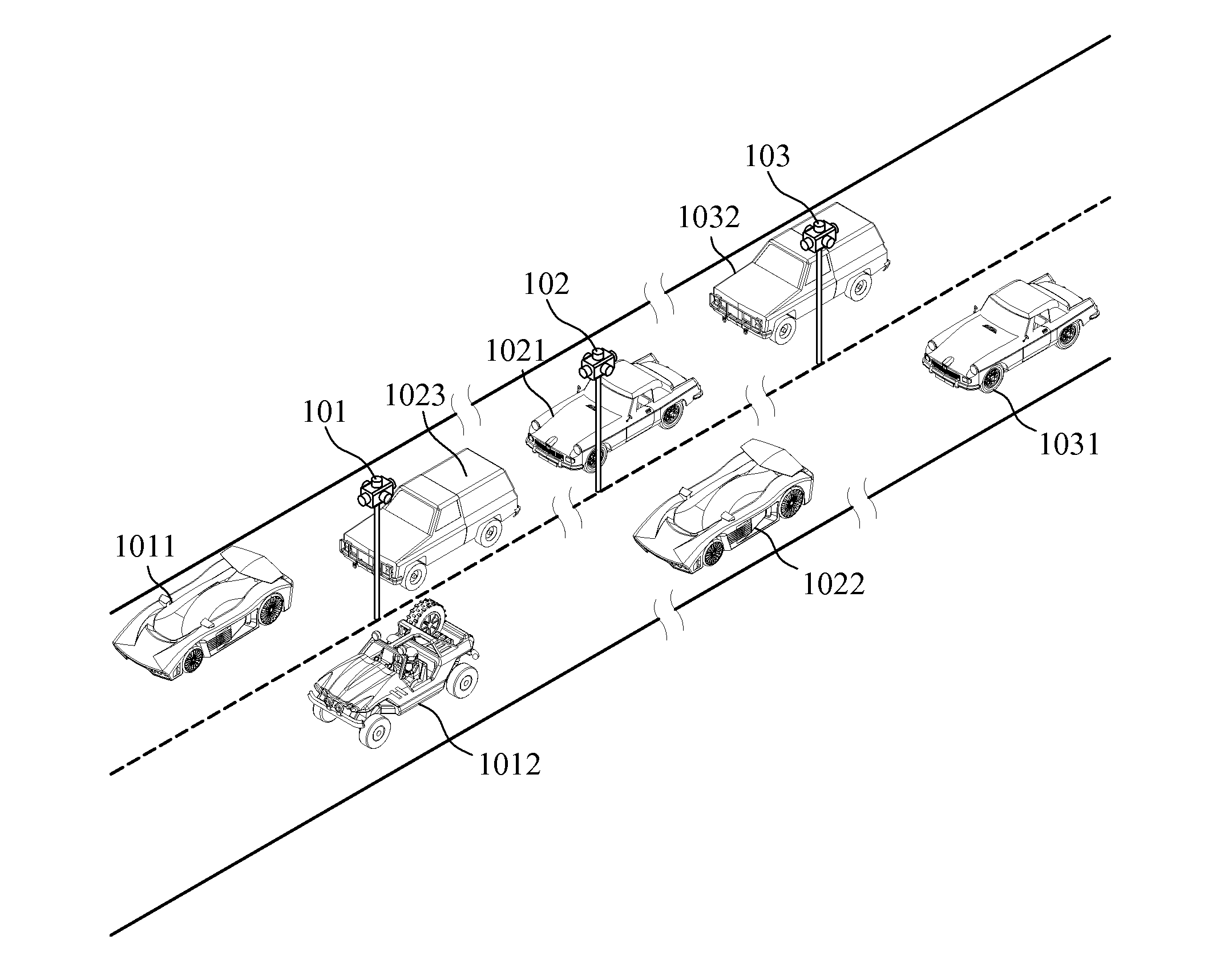
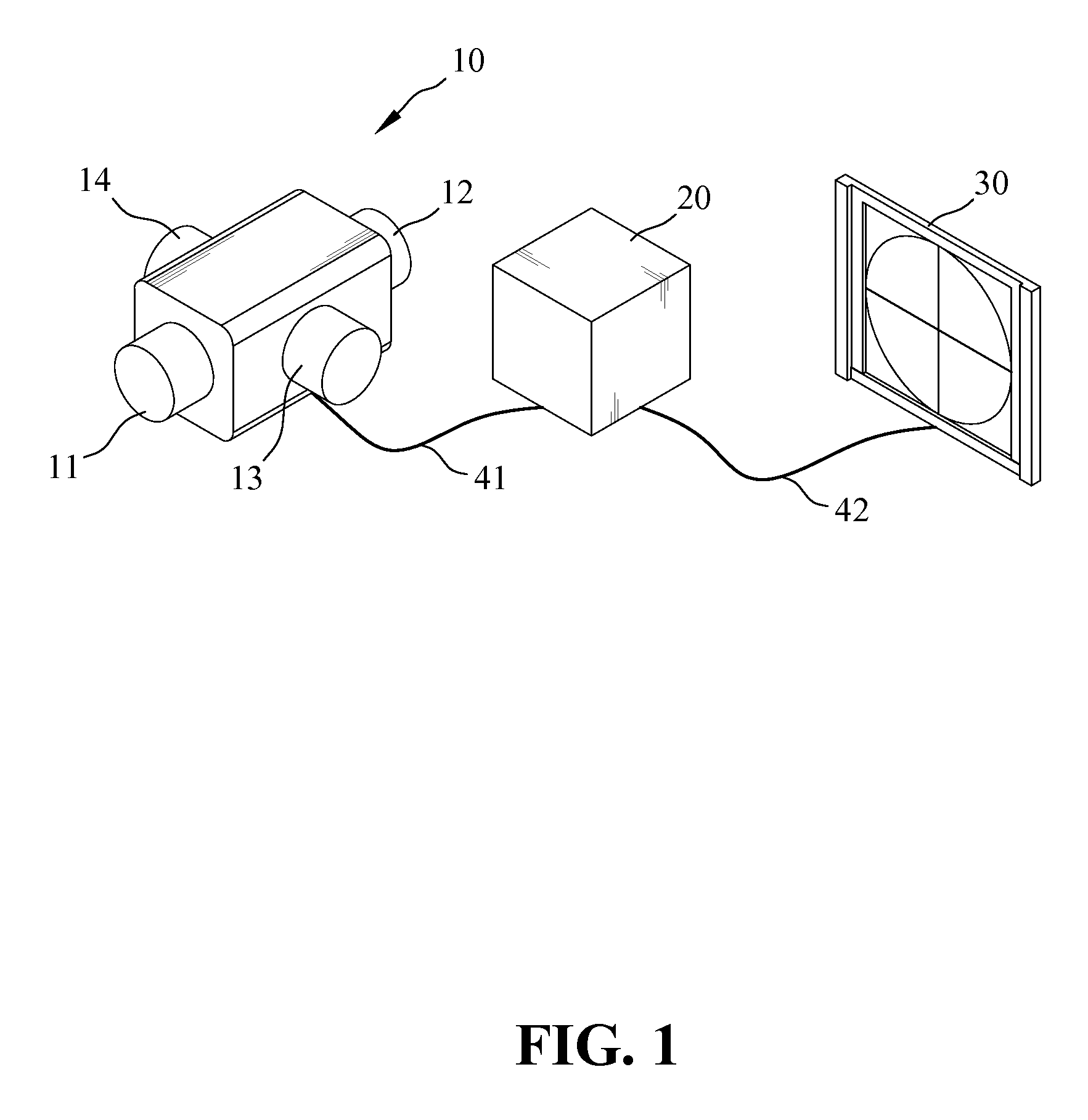
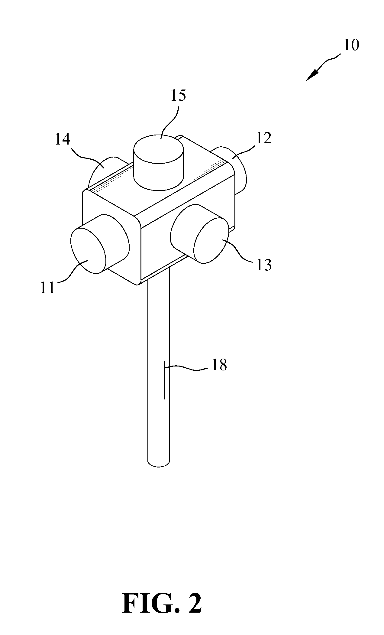
[0022]FIG. 1 is a schematic view of a video radar display system according to an embodiment of the present invention. Referring to FIG. 1, the video radar display system includes a camera array 10, an image processing unit 20, and a display unit 30. The camera array 10 is adapted for photographing toward different directions of the environment so as to capturing a plurality of environmental images. The image processing unit 20 receives the environmental images via a first transmission medium 41 for conducting a process of object recognition, object database connection and environmental reconstruction, for generating an environmental image data. The display unit 30 receives the envir...


PUM


Abstract

A video radar display system is provided. The video radar display system includes a camera array, an image processing unit, and a display unit. The camera array includes a plurality of cameras individually positioned for photographing a plurality of images from a plurality of different directions. The image processing unit receives the photographed images from the camera array for conducting an object recognition process, and referring to an object database to reconstruct an environment, so as to generate object display information. The display unit receives the object display information and displays an image according to the received object display information, or project the image to a monitor or head-up display for displaying. The cameras of the camera array are dual-lens cameras or tri-lens cameras. Specifically, the dual-lens camera has two lenses horizontally provided for capturing two images at the same time for determining the distance.

Description

BACKGROUND OF THE INVENTION[0001]1. Field of the Invention[0002]The present invention relates generally to a video radar display system, and more particularly to a video radar display system adapted for displaying multiple images captured from different directions in an integrated picture.[0003]2. The Prior Arts[0004]It is always very much desired to further improve the driving safety. Some car manufacturers developed to employ infrared (IR) ray, supersonic radar, microwave, or radio frequency wave to detect obstructions nearby the vehicle, so as to alert the driver to pay attention to dangerous road conditions. Such systems include the ACC system for TOYOTA Camry series designed for alerting the front side collision, and the Side Assist System for AUDI series designed for left or right turn alert.[0005]However, it is known that the IR ray and supersonic radar are featured with a small detection range and short application distance, and are likely to be disturbed, while when microwa...

Claims


Application Information

Patent Timeline
IPC IPC(8): H04N7/18
CPCG08G1/015G08G1/0175G06K9/00785H04N7/181G08G1/056G06V20/54
Inventor CHIANG, YAN-HONG
Owner CHIANG YAN HONG
Why Eureka
Try Eureka