Light emitting unit, light emitting module, and display device

a technology of light emitting modules and light emitting units, which is applied in the direction of instruments, discharge tubes, luminescnet screens, etc., can solve the problem of insufficient light emitting efficiency and achieve the effect of improving the efficiency of extraction of light outpu

Inactive Publication Date: 2012-02-23
SHOWA DENKO KK
View PDF4 Cites 34 Cited by
  • Summary
  • Abstract
  • Description
  • Claims
  • Application Information

AI Technical Summary

Benefits of technology

[0036]According to the present invention, it is possible to improve the efficiency of extraction of light outputted from the light emitting unit.

Problems solved by technology

However, in the aforementioned white LED package, not all of light generated in a semiconductor light emitting element is effectively used, but there are some portions where the light is confined to the inside of the package and cannot come out.
However, upon actually manufacturing a prototype of the light emitting unit, sufficient light emitting efficiency could not be obtained with such a configuration.

Method used


Image

  • Light emitting unit, light emitting module, and display device
  • Light emitting unit, light emitting module, and display device
  • Light emitting unit, light emitting module, and display device

Examples


exemplary embodiment 1

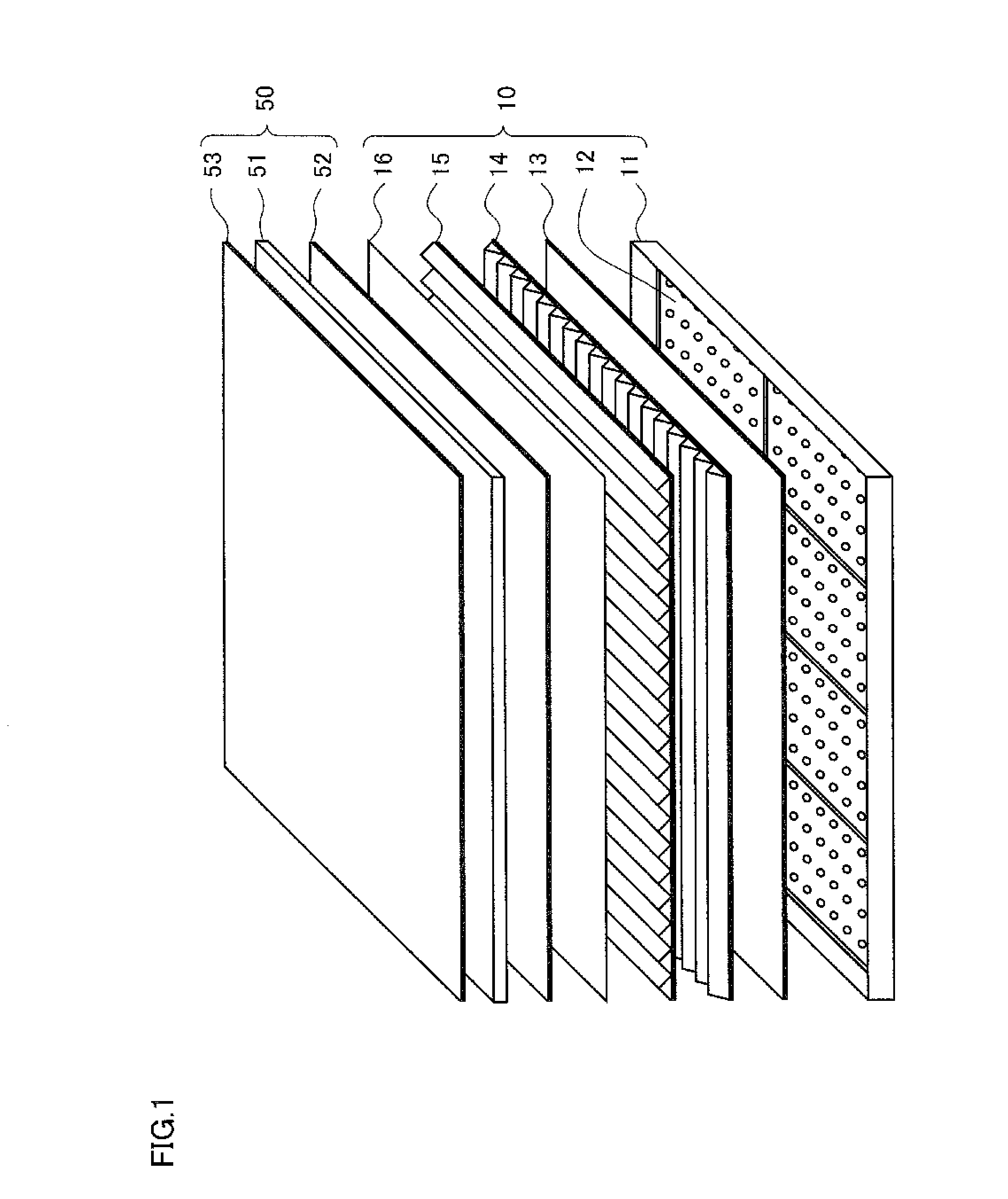
[0051]FIG. 1 is the diagram showing the entire configuration of the liquid crystal display device to which the present exemplary embodiment is applied. The liquid crystal display device includes a liquid crystal display module 50 and a backlight unit 10 provided on a back surface side (in FIG. 1, on a lower portion side) of the liquid crystal display module 50.

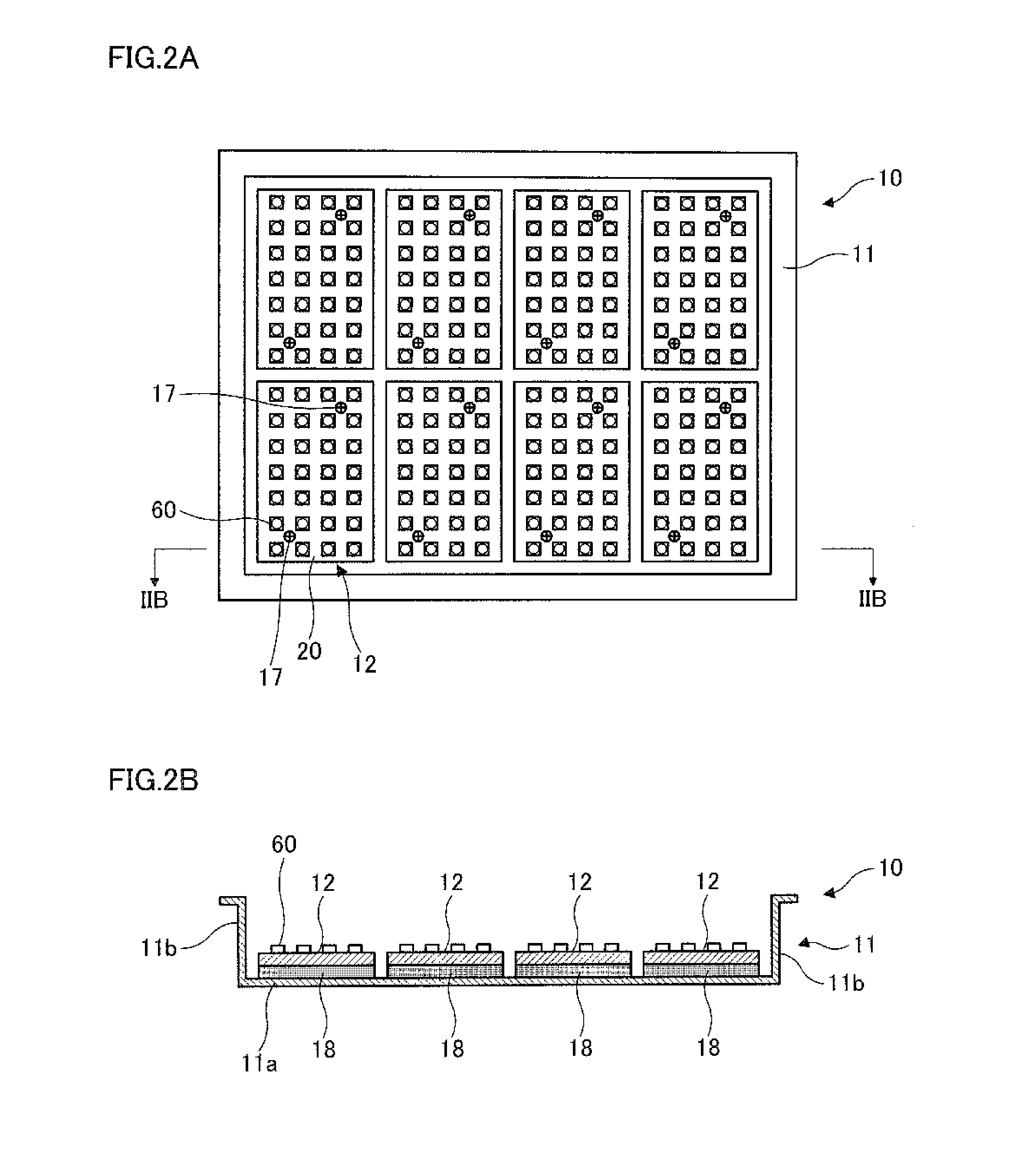
[0052]The backlight unit 10 includes a backlight frame 11 and plural light emitting modules 12 contained in the backlight frame 11, in each of which semiconductor light emitting elements are arranged. The backlight unit 10 also includes, as a laminate of optical films, a diffusing plate 13 that is a plate (or a film) for dispersing or diffusing light to make an entire surface have uniform brightness, and prism sheets 14 and 15 that have a forward light-gathering effect. A luminance-improving film 16 of a diffusion- or reflection-type for improving the luminance is also provided as necessary.

[0053]On the other hand, the liquid ...

exemplary embodiment 2

[0110]FIGS. 5A and 5B are diagrams illustrating a configuration of the light emitting unit 60 of the present exemplary embodiment. Here, FIG. 5A is a top view of the light emitting unit 60, and FIG. 5B is a VB-VB cross-sectional view of FIG. 5A.

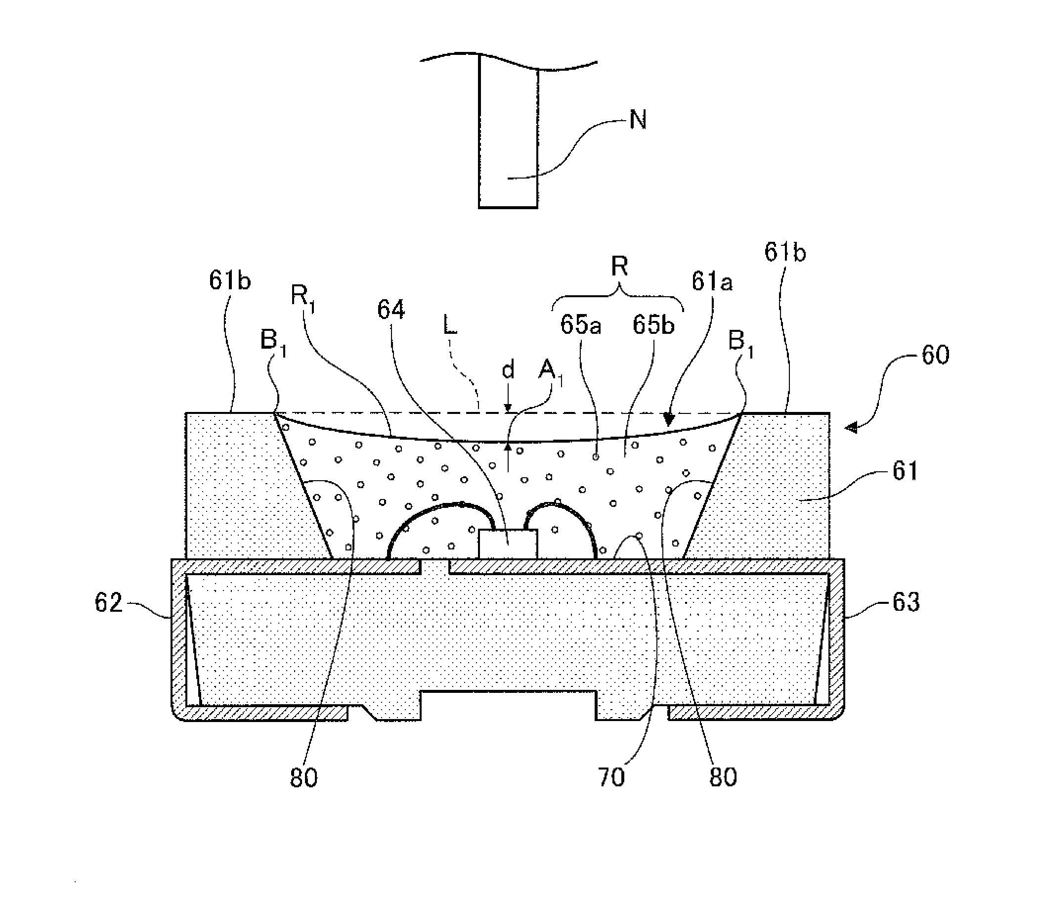
[0111]This light emitting unit 60 includes a resin container 61 in which a recessed portion 61a is formed on an upper portion side thereof, a first anode lead portion 62a, a second anode lead portion 62b, a third anode lead portion 62c and a cathode lead portion 63 formed by a lead frame integrated with the resin container 61, a first semiconductor light emitting element 64a, a second semiconductor light emitting element 64b and a third semiconductor light emitting element 64c attached to a bottom surface 70 of the recessed portion 61a and a sealing resin 65 provided to cover the recessed portion 61a. It should be noted that the sealing resin 65 is omitted in FIG. 5A.

[0112]The resin container 61 is formed by injection molding of a thermoplast...

exemplary embodiment 3

[0145]FIGS. 7A and 7B are diagrams illustrating a configuration of the light emitting unit 60 of the present exemplary embodiment. Here, FIG. 7A is a top view of the light emitting unit 60, and FIG. 7B is a VIIB-VIIB cross-sectional view of FIG. 7A.

[0146]The basic configuration of the light emitting unit 60 is almost similar to that used in the exemplary embodiment 2. However, in this light emitting unit 60, only the first semiconductor light emitting element 64a is mounted, whereas the second semiconductor light emitting element 64b and the third semiconductor light emitting element 64c are not mounted. Here, similar to the exemplary embodiment 2, the first semiconductor light emitting element 64a is attached to the first anode lead portion 62a exposed on the bottom surface 70, and electrically connected to the first anode lead portion 62a and the cathode lead portion 63.

[0147]Further, in the light emitting unit 60, similar to the exemplary embodiment 2, the first semiconductor lig...


PUM


Abstract

A light emitting unit (60) is provided with a resin container (61) in which a recessed portion (61a) is formed, an anode lead portion (62) and a cathode lead portion (63) which are provided so as to be exposed on the bottom surface of the recessed portion (61a), a semiconductor light emitting element (64) attached to the cathode lead portion (63) on the bottom surface (70) of the recessed portion (61a), and a sealing resin (65) provided so as to cover the recessed portion (61a). The resin container (61) is produced from a white resin containing titania as a coloring agent. The anode lead portion (62) and the cathode lead portion (63) are each configured by forming a silver-plated layer with the gloss level set in the range of 0.3-1.0 inclusive on a metal plate based on a copper alloy or the like. Thus, the efficiency of extraction of light outputted from the light emitting unit is improved.

Description

TECHNICAL FIELD[0001]The present invention relates to a light emitting unit, a light emitting module and a display device using a light emitting element.BACKGROUND ART[0002]Recently, since a so-called white LED (LED: light emitting diode) is adopted as a backlight of a liquid crystal display of a cellular phone, production of the white LED is dramatically increased. Here, a white LED package refers to a light emitting unit including a semiconductor light emitting element (LED), which is, for example, formed by arranging a lead frame inside a recessed portion formed on a white resin case so as to be exposed, attaching a semiconductor light emitting element to the lead frame exposed inside the recessed portion and electrically connecting thereof together and forming a sealing resin containing fluorescent bodies in the recessed portion so as to cover the semiconductor light emitting element.[0003]Hereafter, it is expected that the use of the white LED in the backlight of the liquid cry...

Claims


Application Information

Patent Timeline
Patent Type & Authority Applications(United States)
IPC IPC(8): G09F13/04H01J1/70
CPCG02F1/133603H01L33/44H01L33/46H01L33/50H01L33/54H01L2224/45144H01L2224/48091H01L2924/00014H01L2924/00
Inventor HANAWA, KENZOHOSHINA, TAKAHARUTAKEI, TOMOYUKI
Owner SHOWA DENKO KK
Why Eureka
Try Eureka