Light-emitting module, light source device, liquid crystal display device, and method of manufacturing light-emitting module

Active Publication Date: 2012-02-23
PANASONIC INTELLECTUAL PROPERTY MANAGEMENT CO LTD
View PDF7 Cites 49 Cited by
  • Summary
  • Abstract
  • Description
  • Claims
  • Application Information

AI Technical Summary

Benefits of technology

[0011]In the light-emitting module, light source device and liquid crystal display device pertaining to aspects of the present invention, a plurality of element columns, each of which is constituted by light-emitting elements arranged in line, are mounted on a substrate in rows. Here, each element column is individually sealed by a separate sealing member. With this structure, the heat from light-emitting elements sealed by one sealing member is hardly conducted to other sealing members, and each sealing member easily loses the heat since its exterior is in contact with the outer air. As a result, the sealing members hardly have an excessively high temperature on a local basis, and the luminance of LEDs and the excitation efficiency of phosphors hardly decrease. Therefore, unevenness in the luminance and

Problems solved by technology

Another reasoning is that although it is difficult for the central portion of the sealing member to lose heat since it is enclosed by the outer edge portion of the sealing member, it is easy for the outer edge portion of the sealing member to lose heat since its exterior is in contact with the outer air.
The properties of LEDs are

Method used


Image

  • Light-emitting module, light source device, liquid crystal display device, and method of manufacturing light-emitting module
  • Light-emitting module, light source device, liquid crystal display device, and method of manufacturing light-emitting module
  • Light-emitting module, light source device, liquid crystal display device, and method of manufacturing light-emitting module

Examples


first embodiment

(Overall Structure)

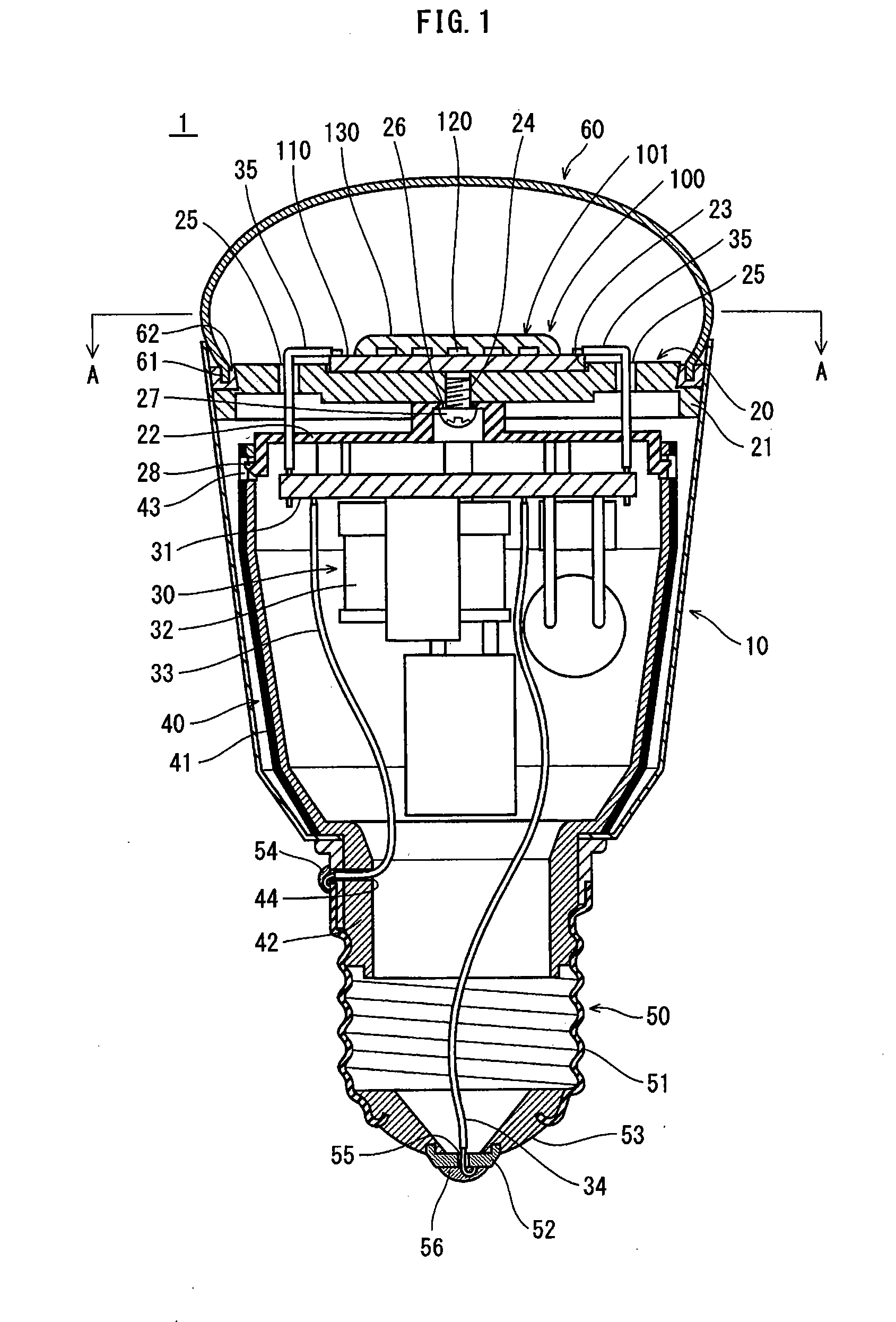
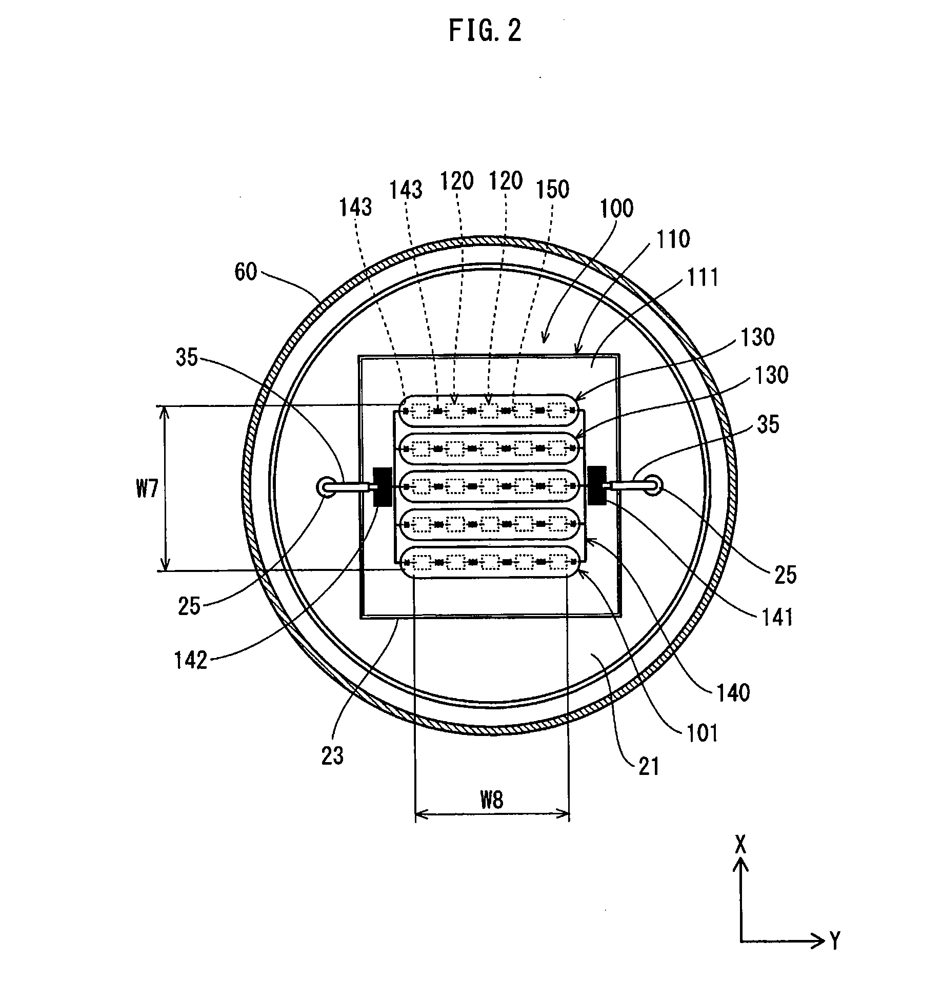
[0040]FIG. 1 is a cross-sectional view showing a light source device pertaining to the present embodiment. FIG. 2 shows a cross section taken along A-A in FIG. 1. As shown in FIG. 1, an LED lamp 1, which is herein described as an example of a light source device pertaining to First Embodiment, includes the following main structural elements: a housing 10; a holder 20; a lighting circuit unit 30; a circuit case 40; a base 50; a globe 60; and an LED module 100, which is herein described as an example of a light-emitting module pertaining to First Embodiment.

(Housing)

[0041]The housing 10 has a shape of, for example, a circular cylinder. The LED module 100 is disposed at one opening of the housing 10. The base 50 is disposes at the other opening of the housing 10. A highly heat-conductive material (e.g., aluminum) is used as a base material of the housing 10, so that the housing 10 functions as a heat dissipating member (heat sink) that dissipates heat from the LED mo...

second embodiment

[0092]FIG. 9 is a cross-sectional view showing a liquid crystal display device pertaining to Second Embodiment. As shown in FIG. 9, a liquid crystal display device 1001 pertaining to Second Embodiment is composed of an edge-lit backlight unit (light source device) 1010, an active-matrix liquid crystal panel 1020, a hosing 1030, and the like. The housing 1030 houses the backlight unit 1010, the liquid crystal panel 1020, and other components.

[0093]The backlight unit 1010 is composed of a housing 1011, a reflecting sheet 1012, a light guide plate 1013, a diffusion sheet 1014, a prism sheet 1015, a polarization sheet 1016, a heat sink 1017, a lighting circuit 1018, a plurality of LED modules 1100 as light-emitting modules pertaining to Second Embodiment, and the like. The hosing 1011 is made up of a main body 1011a and a front frame 1011b.

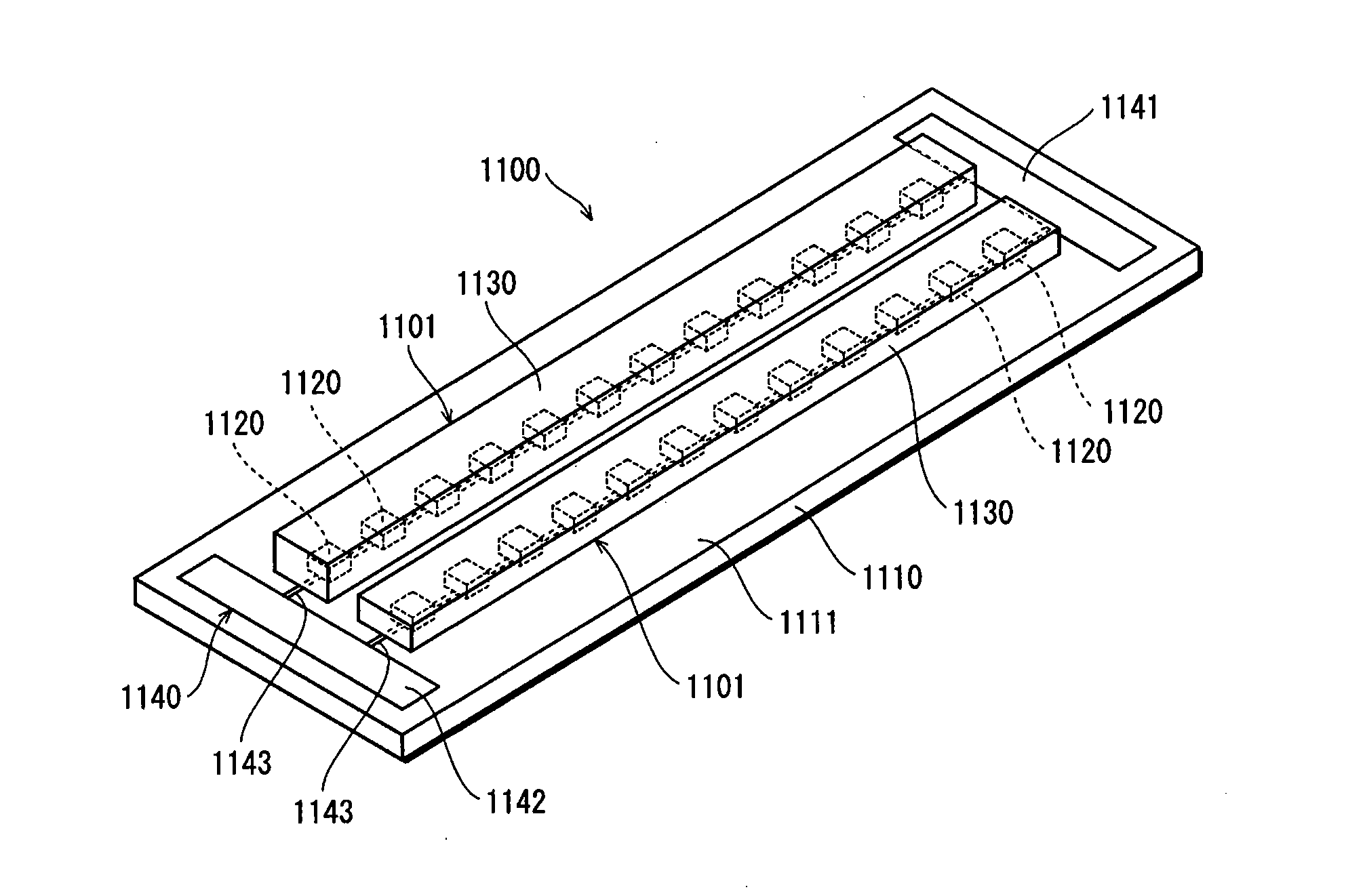
[0094]Each LED module 1100 is composed of a substrate 1110, a plurality of LEDs (light-emitting elements) 1120, and a plurality of sealing members 1...

third embodiment

[0096]FIG. 11 is a perspective view showing a light-emitting module pertaining to Third Embodiment. FIG. 12 is a plan view showing the light-emitting module pertaining to Third Embodiment.

[0097]An LED module used as the light-emitting module pertaining to the present invention may be structured such that all sealing members are joined to a joining member formed on a substrate. For example, as shown in FIG. 11, the LED module 2100 is structured such that each of the sealing members 2130 (of the light-emitting units 2101), which are located in the vicinity of the center of the substrate 2110, has its end portions joined to a joining member 2160. Here, all the sealing members 2130 and the joining member 2160 constitute a framework 2102 having a ladder-like structure. More specifically, as shown in FIG. 12, a plurality of element columns are mounted on the substrate 2110 in parallel rows, each element column including LEDs 2120 arranged in line. Each element column is individually seale...


PUM


Abstract

Provided is a light-emitting module, a light source device and a liquid crystal display device in which unevenness in the luminance and color hardly occurs as compared to conventional technology. A light-emitting module 100 is structured such that a plurality of element columns, each composed of light-emitting elements 120 arranged in line, are mounted on a substrate 110, and each element column is individually sealed by a separate sealing member 130. The light source device and the liquid crystal device each include the above light-emitting module 100.

Description

TECHNICAL FIELD[0001]The present invention relates to a light-emitting module having a plurality of light-emitting elements such as light-emitting diodes (LEDs), a light source device, a liquid crystal display device, and a method of manufacturing the light-emitting module.BACKGROUND ART[0002]In recent years, there is a growing demand for conservation of resources in the field of light source devices such as halogen light bulbs and fluorescent lamps, and many developments are carried out on light-emitting modules using LEDs with power-saving capabilities and long life. In such light-emitting modules, shortage of luminance caused by using the LEDs alone is supplemented by high integration of the LEDs. For example, Patent Literature 1 discloses a light-emitting module in which a plurality of LDS are arranged on a substrate in a matrix and sealed by a sealing member as a whole (see Patent Literature 1).[Citation List][Patent Literature][0003][Patent Literature 1]SUMMARY OF INVENTIONTec...

Claims


Application Information

Patent Timeline
IPC IPC(8): G09F13/04H01J9/22H01J1/62
CPCF21K9/1355F21V29/89F21V3/00F21V17/101F21V19/005F21V19/0055F21Y2101/02F21Y2105/001H01L25/0753H01L33/54H05K3/284H05K2201/10106H01L2224/45144H01L2224/48091H01L2224/48227F21K9/90F21V29/507H01L2924/3025H01L2924/00014H01L2924/00H01L2224/45139F21Y2105/10F21K9/23F21Y2115/10H01L2924/00011H01L2224/45015H01L2924/207H01L2924/01049
Inventor OGATA, TOSHIFUMISUGIURA, KENJIMORIKAWA, MAKOTO
Owner PANASONIC INTELLECTUAL PROPERTY MANAGEMENT CO LTD
Why Eureka
Try Eureka