
Route optimization of a data path between communicating nodes using a route optimization agent

a technology of routing optimization and data path, applied in data switching networks, digital transmission, wireless network protocols, etc., can solve the problems of inefficient routing, high packet delay, and breakage of connection to active ip sessions, and achieve the effect of easy optimization

Inactive Publication Date: 2012-02-23
OPTIS WIRELESS TECH LLC
View PDF3 Cites 78 Cited by
  • Summary
  • Abstract
  • Description
  • Claims
  • Application Information

AI Technical Summary

Benefits of technology

[0106]The second communication node is not involved in the route optimization according to the present invention. Therefore, the appliance of said route optimization does not depend on whether the second communication node supports any kind of protocol. Furthermore, no air resources of the second communication node are used for said route optimization. One further advantage of the route optimization of the current invention is that the downlink and uplink direction of the data exchange is optimized, instead of only one direction as with MIPv6. In addition, since no new home address is established for the route optimization, data paths of ongoing sessions may be easily optimized without needing any further modifications in the system due to a new home address. Also, the location of MN1 is not revealed to MN2.

Problems solved by technology

However, since transport layer connections, such as TCP connections are bound to the IP addresses (and ports) of the communicating nodes, the connection to the active IP sessions breaks if one of the nodes changes its IP address, e.g. due to movement.
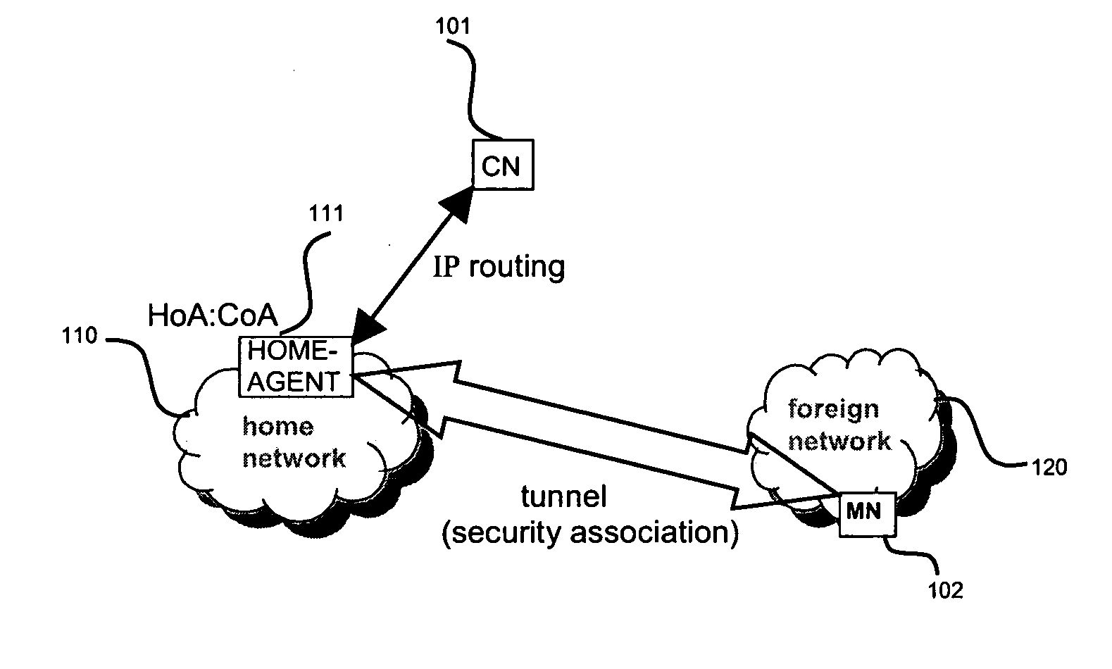
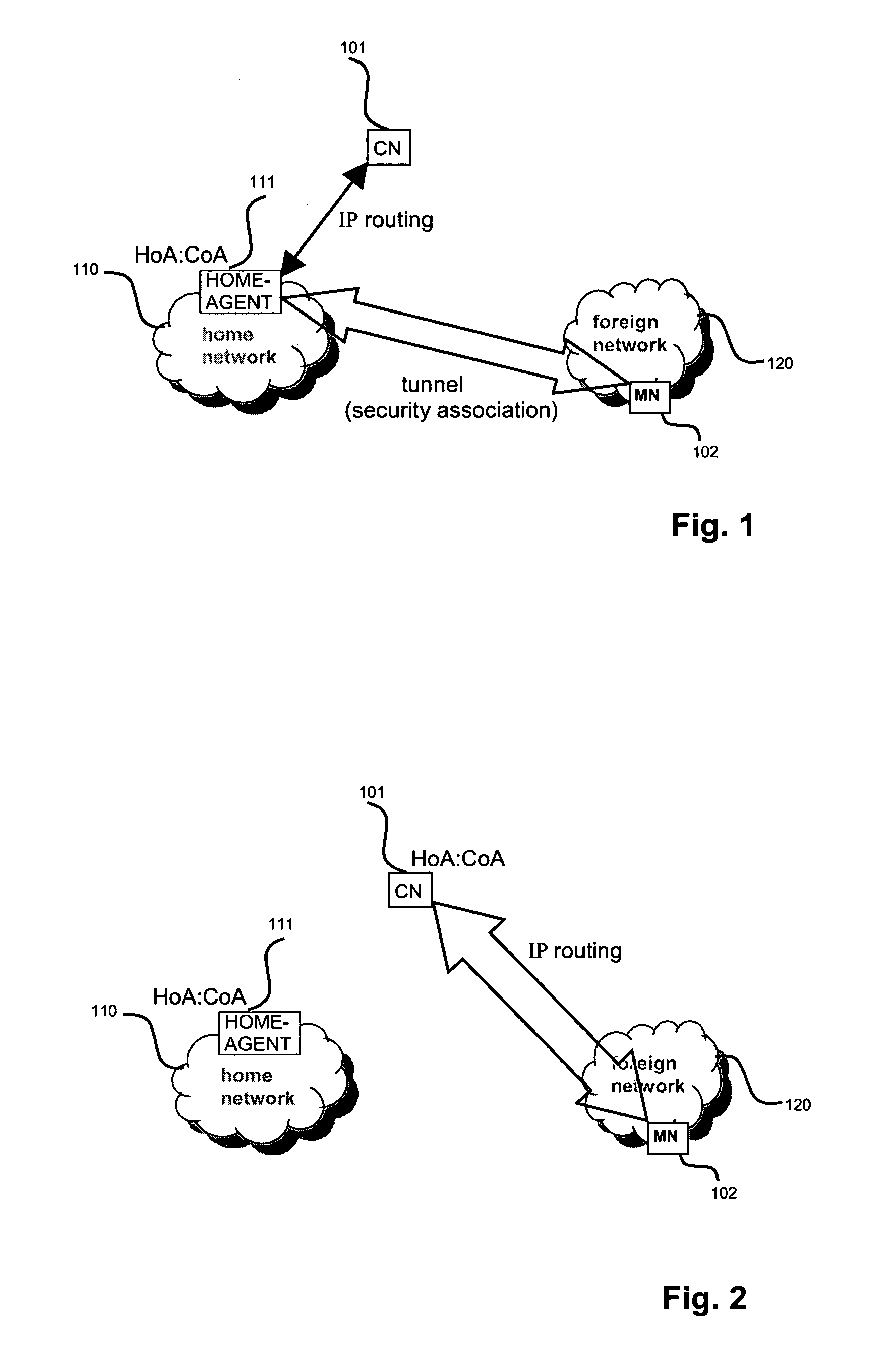
A drawback is that if the mobile node is far away from the home network and the correspondent node is close to the mobile node, the communication path is unnecessarily long, resulting in inefficient routing and high packet delays.
Not every PLMN organisation will implement the complete Management Architecture and related processes.
If there is no roaming agreement between the two networks, i.e. HPLMN and VPLMN, maintenance of service is impossible, and service is denied by the visited network.
In this case, the data packets exchanged between the two nodes are traversing a very long distance, resulting in long delays and inefficient routing.
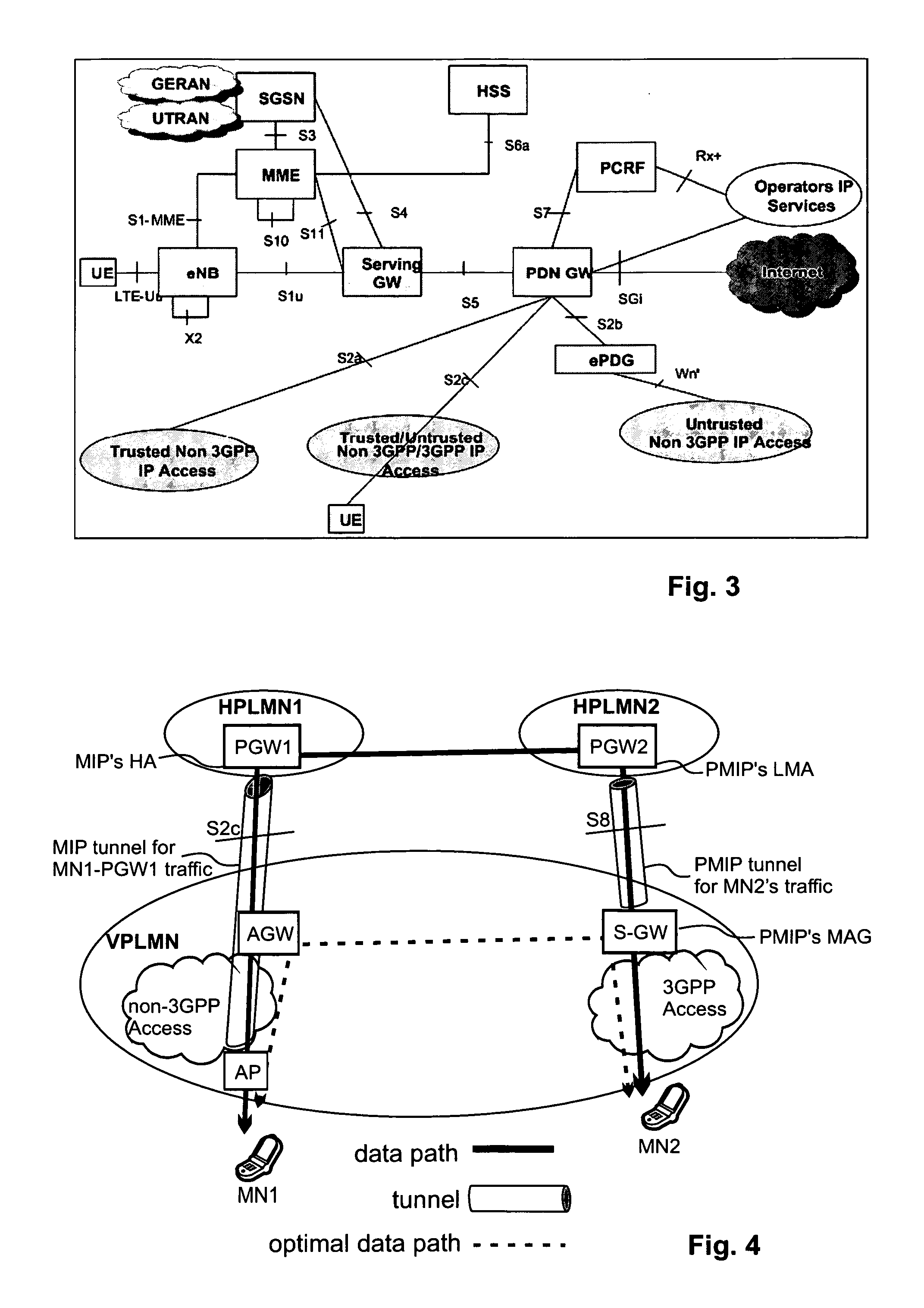
As apparent therefrom, the data route is not optimal and still has long delays and inefficient routing.
Again, the route is not the optimal one.

Method used


Image

  • Route optimization of a data path between communicating nodes using a route optimization agent
  • Route optimization of a data path between communicating nodes using a route optimization agent
  • Route optimization of a data path between communicating nodes using a route optimization agent

Examples


Embodiment Construction

Definitions

[0154]In the following a definition of a few terms frequently used in this document will be provided.

[0155]A mobile node is a physical entity within a communication network. One node may have several functional entities. A functional entity refers to a software or hardware module that implements and / or offers a predetermined set of functions to other functional entities of a node or the network. Nodes may have one or more interfaces that attach the node to a communication facility or medium over which nodes can communicate. Similarly, a network entity may have a logical interface attaching the functional entity to a communication facility or medium over it may communicate with other functional entities or correspondent nodes.

[0156]A communication node may either be a mobile node, such as a mobile phone or laptop, or a fixed node, such as a server.

[0157]An IP tunnel may be defined as the additional encapsulation of a data packet with an IP header, having as corresponding s...


PUM


Abstract

The invention relates to optimizing a data path between two communication nodes. A route optimization agent (ROA) is determined in the current network of the second communication node, preferably on the data path between the two communication nodes. Then, an IP tunnel is established between the first communication node and the ROA, the IP tunnel and the corresponding security association of said IP tunnel being based on the home address of the first communication node in its home network. The first communication node may have two IP tunnels based on the same home address, one to its home agent and one to the ROA. Corresponding routing entries and binding cache entries need to be established in the ROA and the first communication node so that all data packets between the two communication nodes are exchanged via the established IP tunnel over the ROA.

Description

FIELD OF THE INVENTION[0001]The invention relates to a method for optimizing a data path between two communicating nodes in which an optimized data route is established over a route optimization agent in the second communicating nodes' network. Furthermore, the invention relates to a mobile node, a route optimization agent, and a gateway that participate in the invention.TECHNICAL BACKGROUND[0002]Communications systems evolve more and more towards an Internet Protocol (IP)-based network. They typically consist of many interconnected networks, in which speech and data is transmitted from one terminal to another terminal in pieces, so-called packets. IP packets are routed to the destination by routers in a connection-less manner. Therefore, packets comprise IP header and payload information, and the header comprises, amongst other things, a source and destination IP address.[0003]For scalability reasons, an IP network uses a hierarchical addressing scheme. Hence, an IP address does no...

Claims


Application Information

Patent Timeline
IPC IPC(8): H04L12/56
CPCH04W8/082H04W80/04H04W48/16
Inventor VELEV, GENADIBACHMANN, JENSIKEDA, SHINKICHIHIRANO, JUN
Owner OPTIS WIRELESS TECH LLC
Learn More