Method and devices for heating urea-containing materials in vehicle emission control system

a technology of emission control system and urea-containing materials, which is applied in the direction of vehicle heating/cooling devices, machines/engines, energy input, etc., can solve the problems of urea solution, temperature reduction, exhaust gas cooling, etc., and achieve the effect of reducing nitrogen oxide emissions, reducing nitrogen oxides in scr, and efficiently producing ammonia

Inactive Publication Date: 2012-02-23
DOW GLOBAL TECH LLC
View PDF3 Cites 40 Cited by
  • Summary
  • Abstract
  • Description
  • Claims
  • Application Information

AI Technical Summary

Benefits of technology

[0010]The present invention provides an efficient use of an urea-containing material (e.g., an urea solution or a solid urea-containing) for reducing the nitrogen oxide emissions from a diesel engine even when the exhaust temperature and flow rate are low. The invention provides sufficient high temperature for one or any combination of (e.g., all of) the following process steps: (1) vaporization of water, such as excess water (e.g., evaporation of water from an urea solution); (2) thermolysis of urea into NH3 and isocyanic acid HNCO; or (3) hydrolysis of HNCO into NH3 and CO2. The present invention provides such heat by using stored heat, such as stored heat originally generated by a diesel engine. For example, the stored heat may be waste heat of the exhaust gas that has been captured and stored. The stored heat is stored in a heat storage device (i.e., a thermal-energy storage (“TES”) device) containing a thermal energy storage material. The thermal energy storage material may be a phase change material. Preferably, the thermal energy storage material is encapsulated in metal containers, such as metal capsules. The heat storage devices, heat storage systems, materials, and processes employed in the present invention may include one or any combination of the features taught in published U.S. Patent Application Publication Nos. 20090211726 and 20090250189, both of which are incorporated herein by reference in their entireties. The heat storage device is in thermal communication with an ammonia producing reactor so that that heat can be transferred from the heat storage device to the ammonia producing reactor (e.g., when the temperature of the exhaust gas is too low to efficiently produce ammonia or when the temperature of the exhaust gas is too low to efficiently reduce the nitrogen oxides in the SCR reactor). The heat transfer between the heat storage device and the ammonia producing reactor may be supplied using a single-phase heat transfer fluid (“HTF”) or a two-phase HTF. The heat transfer fluid may employ a liquid phase, a vapor phase, or both. The heat transfer fluid may be mechanically pumped or self-pumped. For example, the heat transfer may employ a self-pumped heat transfer fluid including a liquid phase and a vapor phase, such as described in U.S. Provisional Patent Application No. 61 / 245,767 (filed on Sep. 25, 2009 by Soukhojak et al.), the contents of which is incorporated herein by reference in its entirety.

Problems solved by technology

There are however some disadvantages using the urea solution in this application.
If this solution is injected directly into the ammonia producing reactor, the excess water will cause cooling of the exhaust gas, as the excess water consumes heat (e.g., latent heat of vaporization and sensible heat).
This may result in a reduction in temperature such that the ammonia producing reactor and or the SCR reactor does not function efficiently, especially in situations when the temperature where the urea solution is sprayed is relatively low (e.g., about 300° C. or less, or about 250° C. or less).
When this happens, it can result in a solid deposit formation and / or suboptimal temperature in the SCR reactor.
This cooling effect can also result in higher fuel consumption due to high degree of exhaust gas recirculation (EGR) needed to keep the amount of emitted NOx low, since EGR remains the only NOx emission reducing means when the SCR reaction is too slow due to low temperatures in the SCR reactor.
The fuel efficiency of a vehicle is being compromised due to the extra and unnecessary water weight in the urea solution a vehicle has to carry.
The heat generation requirement adds a parasitic load for the engine and the alternator, which in turn reduces the fuel efficiency of the vehicle.

Method used


Image

  • Method and devices for heating urea-containing materials in vehicle emission control system
  • Method and devices for heating urea-containing materials in vehicle emission control system
  • Method and devices for heating urea-containing materials in vehicle emission control system

Examples


Embodiment Construction

[0025]In the following detailed description, the specific embodiments of the present invention are described in connection with its preferred embodiments. However, to the extent that the following description is specific to a particular embodiment or a particular use of the present techniques, it is intended to be illustrative only and merely provides a concise description of the exemplary embodiments. Accordingly, the invention is not limited to the specific embodiments described below, but rather; the invention includes all alternatives, modifications, and equivalents falling within the true scope of the appended claims.

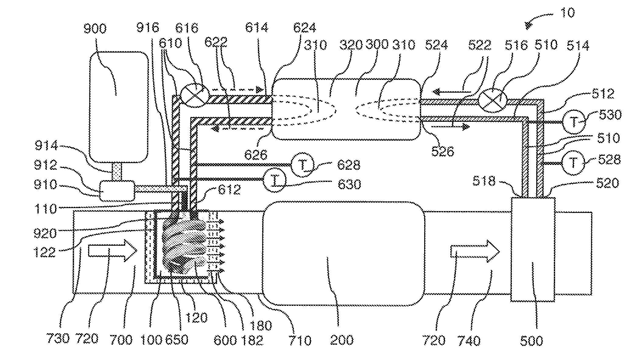
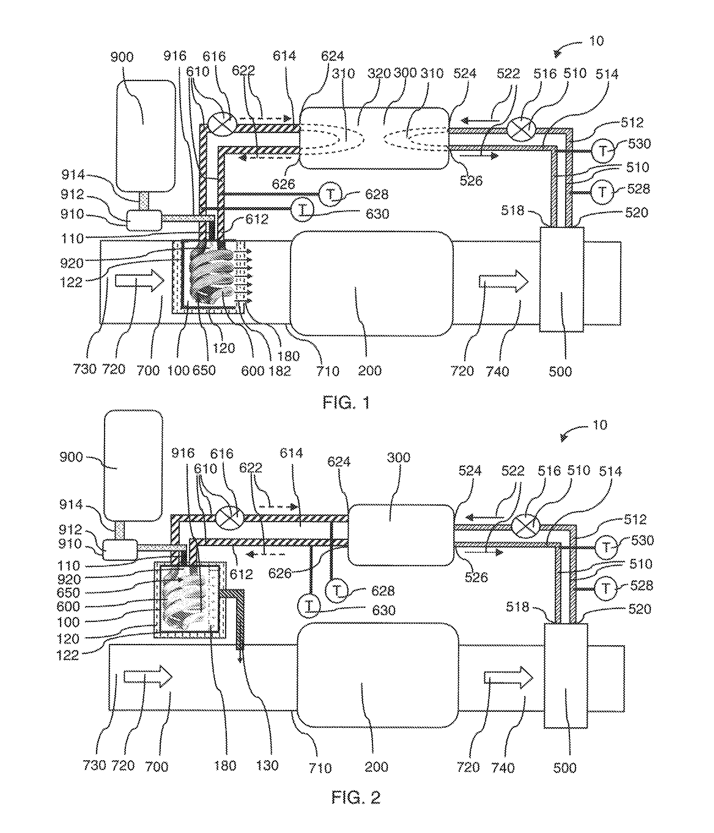
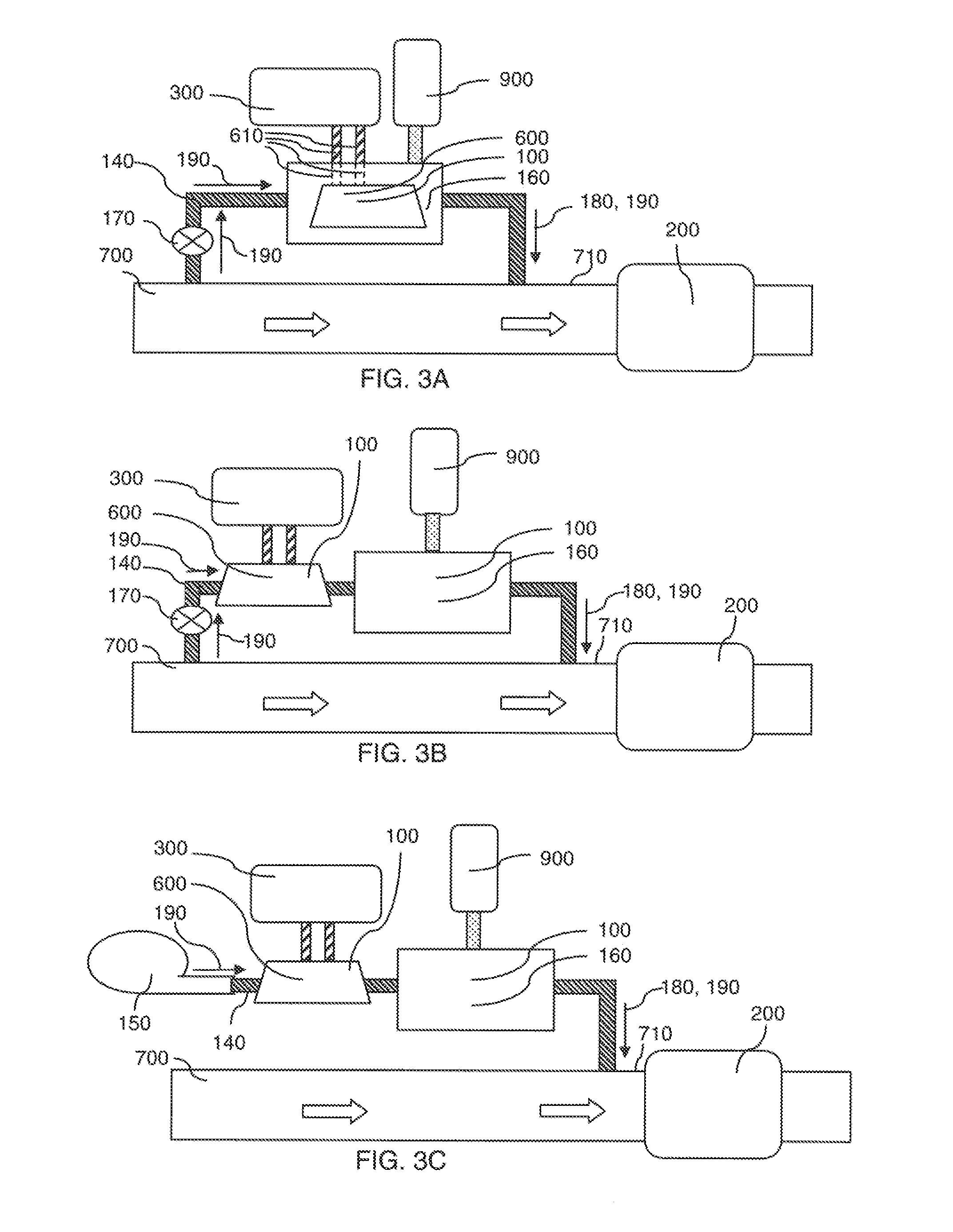
[0026]One or more of the problems associated with removing nitrogen oxides from an exhaust gas having a low temperature, may be overcome using a system that includes a heat storage device for providing heat to a gas producing reactor so that a reductant gas is efficiently produced from a solid or liquid reducing material. By way of example, the solid or liquid redu...


PUM

PropertyMeasurementUnit
liquidus temperatureaaaaaaaaaa
temperatureaaaaaaaaaa
solid surface temperatureaaaaaaaaaa

Abstract

The invention relates to systems and methods for heating a solid or liquid reducing material such as an urea-containing material for NOx selective catalytic reduction (‘SCR’) using a heat stored in a thermal energy storage material, such as a phase change material. The stored heat may be heat from an exhaust waste, such as from an exhaust gas of an internal combustion engine. The reducing material may be a solid reducing material. Other reducing materials include aqueous solutions such as an aqueous solution containing, consisting essentially of, or consisting of urea and water. In one aspect, the process may include a step of evaporating an aqueous solution of urea for immediate urea hydrolysis.

Description

CLAIM OF BENEFIT OF FILING DATE[0001]The present application claims the benefit of the filing date of U.S. Provisional Application Ser. Nos. 61 / 375,077 filed Aug. 19, 2010 and 61 / 375,080 filed Aug. 19, 2010, which are both incorporated herein by reference in their entirety for all purposes.FIELD OF THE INVENTION[0002]The present invention relates to a method for generating a reductant gas, such as ammonia, from a solid or liquid reducing material, such as an urea-containing material, for NOx selective catalytic reduction (‘SCR’) using an exhaust waste heat stored in a thermal energy storage material, such as a phase change material. More specifically, the present invention relates to methods for evaporation of a liquid reducing material (e.g., an aqueous solution of urea and immediate urea hydrolysis), and to methods for heating a solid reducing material.BACKGROUND OF THE INVENTION[0003]Industry in general has been actively seeking a novel approach to capture and store waste heat ef...

Claims


Application Information

Patent Timeline
Patent Type & Authority Applications(United States)
IPC IPC(8): B01D53/94C01B21/02F28D15/00B01J19/00
CPCB01B1/005B01D53/9418B01D2251/206B01D2251/2067C01C1/086F01N3/2066F28D15/0266F01N2240/10F01N2240/25F01N2610/02F01N2610/10Y02T10/24F01N2240/02Y02T10/12Y02P20/129Y02A50/20B01D53/94C01C1/08F01N3/20
Inventor SOUKHOJAK, ANDREYBANK, DAVID H.
Owner DOW GLOBAL TECH LLC
Why Eureka
Try Eureka