Pulsed therapeutic light system and method

a technology of therapeutic light and light source, which is applied in the field of pulsed therapeutic light system and method, can solve the problems of relatively low power density of leds and insufficient power density of typical state of the art leds to achieve effective thermal effects

Inactive Publication Date: 2012-02-23
CYNOSURE
View PDF16 Cites 31 Cited by
  • Summary
  • Abstract
  • Description
  • Claims
  • Application Information

AI Technical Summary

Problems solved by technology

Their drawback is their relatively lower power density.
Typical state of the art LEDs do not have enough power density to achieve effective thermal treatment modalities where at least a subset volume of the skin is at an elevated temperature above normal tissue temperature.

Method used


Image

  • Pulsed therapeutic light system and method
  • Pulsed therapeutic light system and method
  • Pulsed therapeutic light system and method

Examples


Embodiment Construction

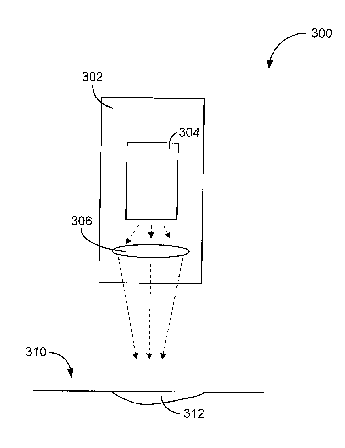
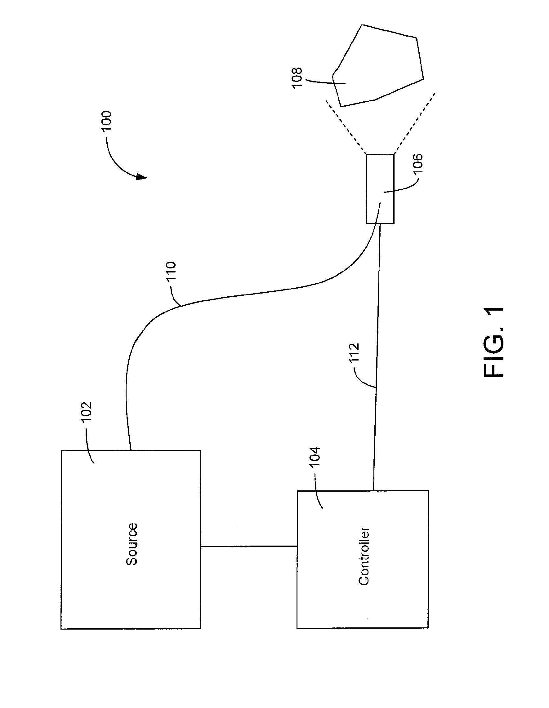
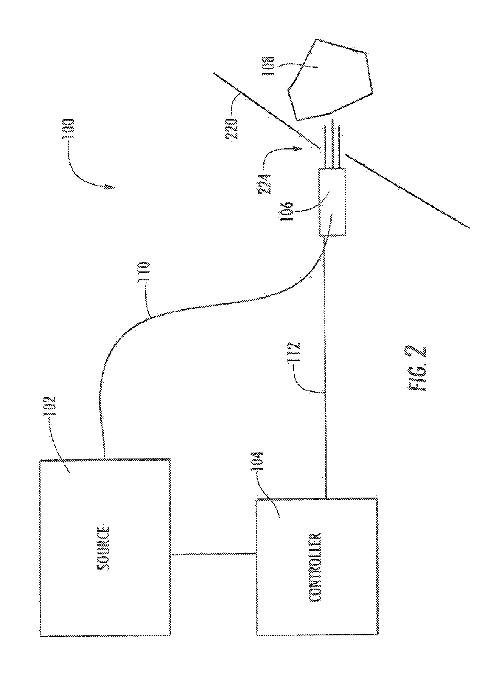
[0030]Referring generally to the figures, systems and methods for delivering therapeutic light to a treatment region using light emitting diodes (LEDs) is shown. The LEDs may be driven in a pulsed mode to provide power that is above the normal continuous operating level for the LEDs. The LEDs may be turned on at the increased operating level for a short period of time (e.g., from 0.5 to 50 ms), followed by a longer period of time (e.g., hundreds of milliseconds) between pulses, allowing the accumulated heat from the on time to dissipate. This allows for the LED source to be used a suitable light source for a light based dermatological treatments in place of lasers and IPLs. The therapeutic light may heat the treatment region such that the heating results in a chemical or physical change to the tissue in the treatment region (e.g., an ablation, cauterization, melting, shrinkage, lipolysis, thermal damage, or another chemical or physical change). The tissue may include collagen, and t...


PUM


Abstract

In one aspect, a method is disclosed of delivering therapeutic light to a treatment region to effect heating in the treatment region. The method includes providing a light emitting diode and driving the light emitting diode to generate therapeutic light during a pulse period. The method further includes directing the therapeutic light to the treatment region at an average power density of about 200 W / cm2 or more at the treatment region during the pulse period and maintaining the light emitting diode in a non-emitting state for a recovery period which is longer than the pulse period.

Description

CROSS-REFERENCE TO RELATED PATENT APPLICATIONS[0001]The present application claims benefit of U.S. Provisional Patent Application Ser. No. 61 / 157,862 filed Mar. 5, 2009, the contents of which is incorporated by a reference herein in its entirety.BACKGROUND[0002]Many light based dermatological treatments are performed currently with lasers or pulsed flashlamps / Intense Pulsed Light (IPL). Some professional grade devices used in dermatological treatments require peak power density between, e.g., 200 and 20,000 W / cm2 delivered in pulse durations between, e.g., 0.5 and 50 ms.[0003]Light emitting diodes (LED) are semiconductor light sources that are typically lower cost and more robust than lasers and IPLs. Their drawback is their relatively lower power density. The peak power specifications of some available state of the art LED devices (e.g. 130 W / cm2, reported in Journal of Display Technology 2007, Vol. 3, pages 160-175) approach the low end of the peak power density range for lasers o...

Claims


Application Information

Patent Timeline
Patent Type & Authority Applications(United States)
IPC IPC(8): A61N5/06A61B18/18
CPCA61B18/203A61N2005/0651A61B2018/1807A61B2018/00452
Inventor WELCHES, RICHARD SHAUNMIRKOV, MIRKOSIERRA, RAFAEL ARMANDO
Owner CYNOSURE
Why Eureka
Try Eureka