Method and apparatus for continuously carbonizing materials

Inactive Publication Date: 2012-03-01
ENERGY INDEPENDENCE OF AMERICA
View PDF1 Cites 3 Cited by
  • Summary
  • Abstract
  • Description
  • Claims
  • Application Information

AI Technical Summary

Benefits of technology

[0015]Still another object of the present invention is to lower capital and operating costs in order to make the invention both technically as well as economically viable.
[0016]Further still, another object of the instant invention is to minimize the use of special, expe

Problems solved by technology

These defects were in the following areas:The makeup structure of the coking chamber;Heat transfer during cokemaking operation;Maintenance of the outer and inner walls of the coking chamber; andHigh capital and operating costs.
Also, there is the issue of supporting inner wall 39 within chamber 10; it is conceivable that inner wall 39 can be supported at the charging end, which is at room temperature; however, it is inconceivable that inner wall 39 can be supported at the hot discharge end, as it will interfere with the discharging of the coke at the hot end.
With respect to the issue of interconnections between each tile in a row of tiles and the issue prevalent between rows that ever change in dimension by virtue of the required taper of each row of tiles, it was evident that such structure would not be dependable when inner wall 39 experiences cycles of expansion when heated, causing the joints to open and thereby inviting leakage towards steel shell 49, which can result in h

Method used


Image

  • Method and apparatus for continuously carbonizing materials
  • Method and apparatus for continuously carbonizing materials
  • Method and apparatus for continuously carbonizing materials

Examples


Example

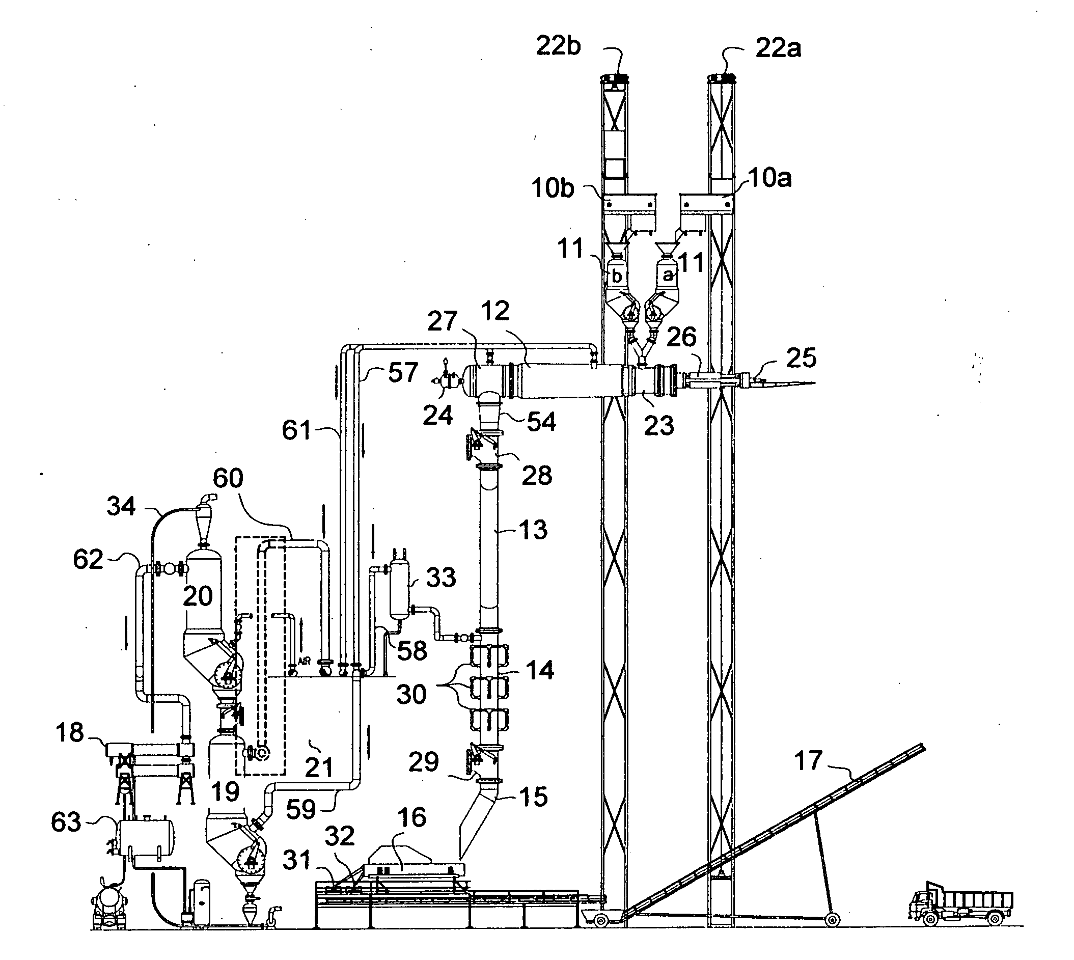
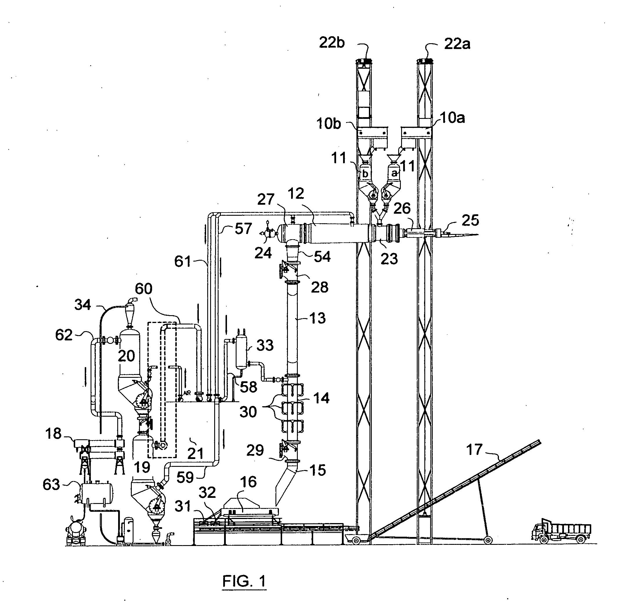
[0024]Reference is now made to the accompanying drawings to enable the detailed description of the instant invention with the aid of numerals. These drawings form a part of the specification wherein like reference characters designate corresponding parts in the various views. By way of example, the material to be carbonized in this description will be directed towards the use of coal and its conversion into coke, which is mainly used in the making of blast-furnace iron, and also it is to be noted that the embodiments shown herein are for the purpose of description and not limitation.

DETAILED DESCRIPTION OF THE DRAWINGS

[0025]Referring to FIG. 1, which illustrates a side elevation of the miscellaneous equipment: numerals 10a and 10b represent two distribution conveyors; numerals 11a and 11b, two feed hoppers; numeral 12, a pyrolyzer (referred to as coking chamber 12); numeral 13, a downcomer; numeral 14, a coke quenching chamber; numeral 15, a coke chute; numeral 16, a coke screen; nu...


PUM


Abstract

A method and apparatus for continuously carbonizing materials while co-producing gases in a coking chamber closed to the atmosphere, having a charger at one end comprising a pushing ram surrounding a mandrel that surrounds an air or oxygen injection lance. The other end of the coking chamber collects and separates coke from gases, with coke directed to a closed quenching chamber and gases directed to a cleanup. Thermal energy for converting coal into coke derives from combusting some metallurgical coal by said lance. In the case of producing coke from metallurgical coal, which is expensive because of limited supply, the herein method and apparatus are configured to separately charge a low-cost, abundant, carbonizing material and expensive metallurgical coal so that metallurgical coal surrounds the low-cost carbonizing material, and a lance combusts the low-cost carbonizing material, releasing thermal energy that heats metallurgical coal under reducing conditions, producing specification coke and gases more economically. After cleanup, gases are used as chemical feedstock or fuel. The word “coke” herein used may also be referred to as “charcoal” or “char.”

Description

INTRODUCTION[0001]The present invention disclosed herein is an improvement of Applicant's patent entitled “Apparatus for Carbonizing Material,” bearing U.S. Pat. No. 5,639,353, issued on Jun. 17, 1997, hereinafter referred to as the “referenced patent.”BACKGROUND[0002]Referring to the drawings, the specification, and the claims disclosed in the referenced patent, certain major and critical defects were identified when the reference patent was attempted to be put into practice. These defects were in the following areas:[0003]The makeup structure of the coking chamber;[0004]Heat transfer during cokemaking operation;[0005]Maintenance of the outer and inner walls of the coking chamber; and[0006]High capital and operating costs.Defects in the Makeup Structure of the Coking Chamber[0007]As shown in Supplement Figures A and B, heating tiles 40, which form walls 38 and 39, possess a great number of wall joints that must be sealed, especially in view of the operation being conducted at a pos...

Claims


Application Information

Patent Timeline
IPC IPC(8): C10B7/00C05F11/02C09K3/00C10B57/04C10J3/00
CPCC05D7/00C05F11/02C10B57/04C10B49/02C10B7/00
Inventor CALDERON, ALBERTLAUBIS, TERRY JAMES
Owner ENERGY INDEPENDENCE OF AMERICA
Why Eureka
Try Eureka