Rear shock-absorbing device

Inactive Publication Date: 2012-03-01
KIND SHOCK HI-TECH CO LTD
View PDF8 Cites 28 Cited by
  • Summary
  • Abstract
  • Description
  • Claims
  • Application Information

AI Technical Summary

Benefits of technology

[0010]The primary object of the present invention is to provide a rear shock-absorbing device wherein the first and second tubes are located in the center of the first and second cylinders, and first and second paths are defined between the two tubes so as to increase the length of the path for the hydraulic liquid to increase the shock-absorbing feature and keep the pressure between the first and second cylinders stable.
[0011]A second object of the present invention is to provide a rear shock-absorbing device wherein the first and second tubes are cooperated with a plug to control the volume of the hydraulic liquid, such that the return speed of the shock-abso

Problems solved by technology

However, the liquid in the second cylinder which is a single cylinder and the spring has fixed spring force, so that when minor shocks are applied to the shock-absorbing device of the first example, the spring is not responsive to the minor shocks which are transferred to the cyclist directly.
In other words, when op

Method used


Image

  • Rear shock-absorbing device
  • Rear shock-absorbing device
  • Rear shock-absorbing device

Examples


second embodiment

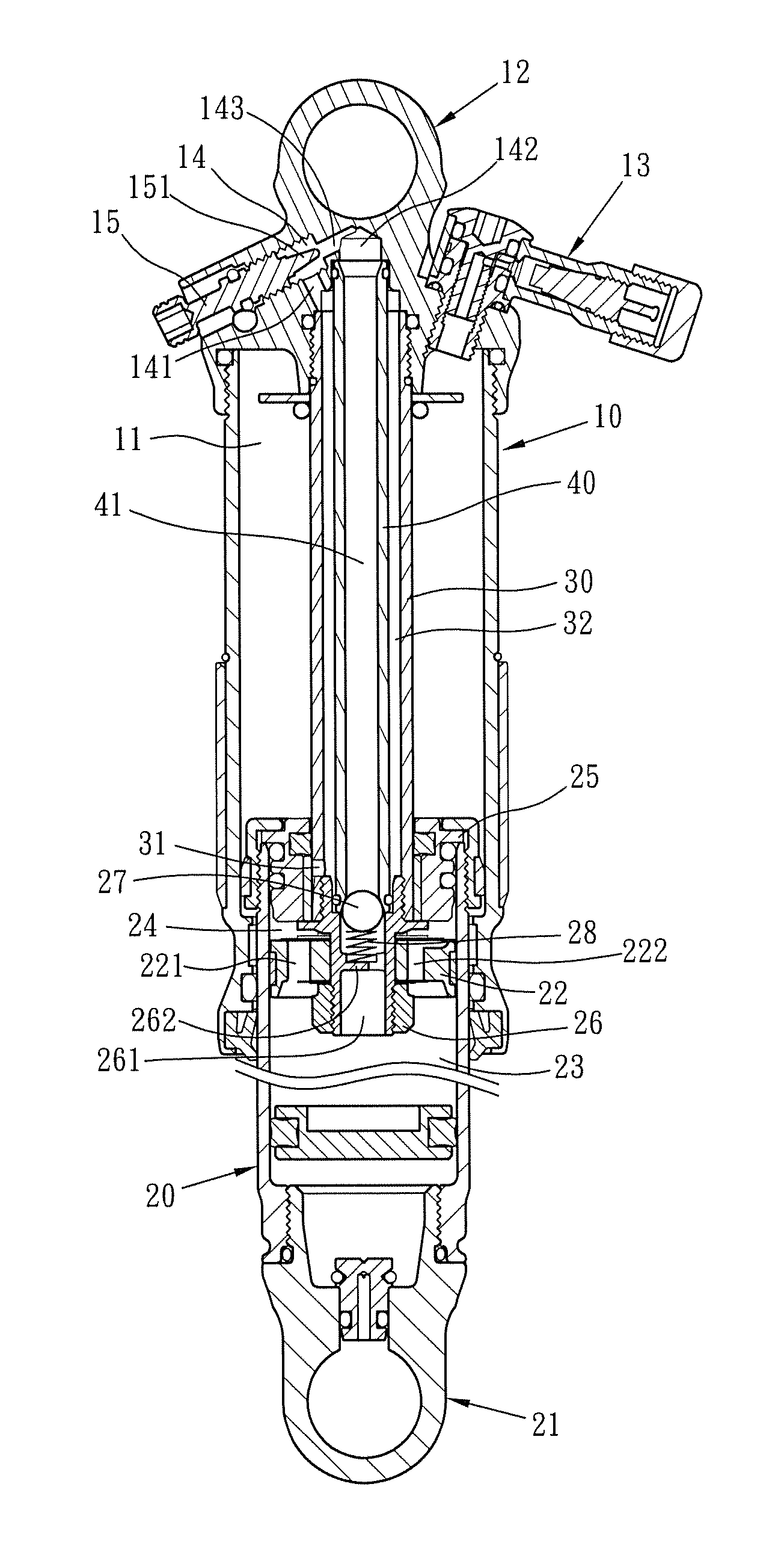
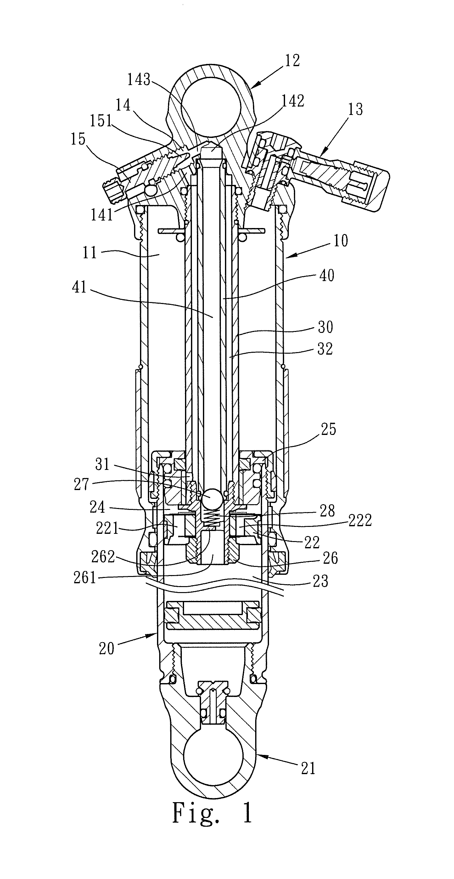
[0039]As shown in FIGS. 5 and 6, which show the present invention, wherein the plug 15 is adjusted to let the cone-shaped section 151 block the passage 143 to control the volume passing through the passage 143. When shocks are applied to the shock-absorbing device, the first and second cylinders 10, 20 move relatively, and the first piston 22 and the first and second tubes 30, 40 move to the second cylinder 20. The hydraulic liquid in the second room 23 partially flows into the third room 24 via the first hole 221 to absorb the shocks. Because the cone-shaped section 151 blocks the passage 143, the hydraulic liquid cannot enter the second path 41 via the passage 143, so that the speed of the compression of the rear shock-absorbing device does not change. When the shocks disappear, the pressurized air in the first room 11 pushes the second cylinder 20 downward and the hydraulic liquid in the second path 41 is not sufficient to push the sealing member 27. In the meanwhile, the hydraul...

third embodiment

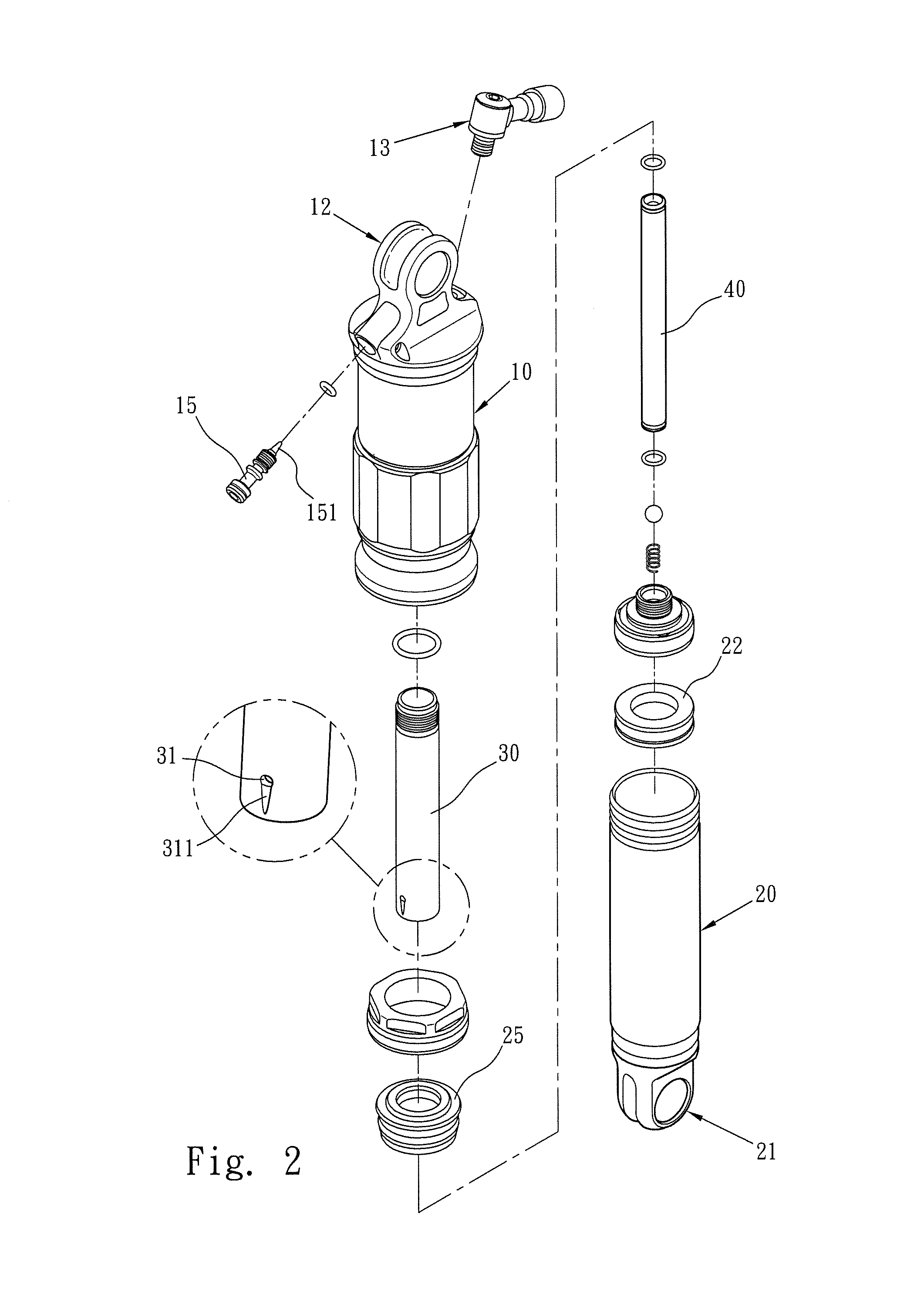
[0040]It is noted that the first cylinder 10 and the first installation unit 12, and the second cylinder 20 and the second installation unit 21 can be individual parts which are connected to each other by known methods. FIG. 7 shows the present invention wherein the first cylinder 10 and the first installation unit 12, and the second cylinder 20 and the second installation unit 21 are integrally formed with each other.

fourth embodiment

[0041]FIGS. 8 to 12 show the fourth embodiment wherein the sealing member 27 and the resilient member 28 located between the second path 41 and the connection member 26 are omitted, and a resilient member 16 is mounted to the first and second cylinders 10, 20. The first installation unit 12 has an adjustment device 50 on a side thereof. The resilient member 16 is a spring.

[0042]The adjustment device 50 has multiple recesses, multiple paths and a third cylinder 60. A first recess 51 and a second recess 52 are radially defined in an inside of the first installation unit 12, and a third recess 53 and a fourth recess 54 are radially defined in the inside of the first installation unit 12 and located opposite to the first and second recesses 51, 52. The first and third recesses 51, 53 have the same diameter, and the second and fourth recesses 51, 54 have the same diameter which is larger than the diameter of the first and third recesses 51, 53. The first, second, third and fourth recesse...


PUM


Abstract

A shock-absorbing device includes a first cylinder with a first room defined therein and a room is defined in an end of the first cylinder. A second cylinder extends into the first cylinder and has a first piston so as to define a third room and a third room. Hydraulic liquid is filled in the second and third rooms. A first tube and a second tube extending through the first tube are located in the first room. A first path and a second path communicate with the recess. The first and second tubes extend into the second cylinder and are connected to the first piston. When the first and second cylinders are relative moved, the hydraulic liquid is controlled to flow or not flow between the first and second paths so as to absorb different levels of shocks, and the speed that the shock-absorbing device returns can be adjusted.

Description

FIELD OF THE INVENTION[0001]The present invention relates to a rear shock-absorbing device, and more particularly, to a bicycle rear shock-absorbing device having multiple paths for the hydraulic liquid flowing therethrough to absorb larger shocks and increasing return speed of the shock-absorbing device.BACKGROUND OF THE INVENTION[0002]The conventional shock-absorbing device for bicycles is focused on absorbing shocks transferred from the road to improve the comfort of the users in the vehicle.[0003]The bicycle shock-absorbing devices include the front shock-absorbing device and the rear shock-absorbing device, and both of which can be operated by hydraulic or pneumatic media, or both.[0004]Taiwan Utility Model Patent Application No. 098217431 discloses a first cylinder having a first installation end and a first open end, wherein the first installation end is connected to the bicycle frame. A piston rod is received in the first installation end. The piston rod includes a first end...

Claims


Application Information

Patent Timeline
IPC IPC(8): B62K25/04B60G15/06F16F13/00F16F9/16
CPCF16F9/44F16F9/063F16F9/5165F16F9/182
Inventor HSU, JUNG YU
Owner KIND SHOCK HI-TECH CO LTD
Why Eureka
Try Eureka