
Video signal skew

a video signal and skew technology, applied in the field of video signal skew, can solve the problems of degrading the image generated by the video display device, appearing ‘, and more noticeable colour split problems, so as to reduce the skew and increase the length of the video signal transmission path

Inactive Publication Date: 2007-10-02
ADDER TECHNOLOGY
View PDF9 Cites 28 Cited by
  • Summary
  • Abstract
  • Description
  • Claims
  • Application Information

AI Technical Summary

Benefits of technology

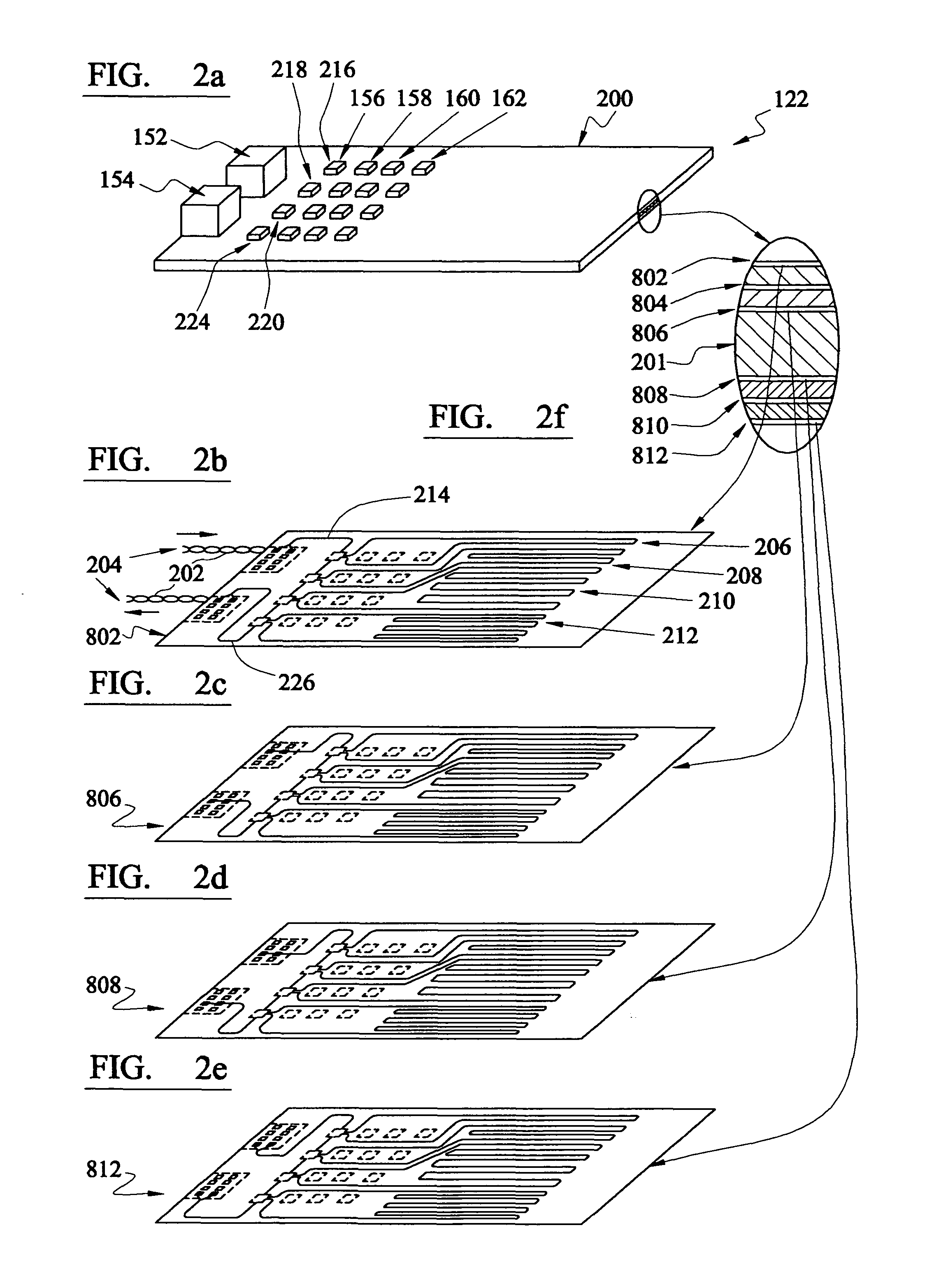
[0009]According to a first aspect of the present invention, there is provided a device for reducing skew between colour video signals transmitted over at least two different video cables, the device including a plurality of video signal transmission tracks connectable to at least one of the video cables to increase the video signal transmission path length thereby more closely matching the total video signal path length for each of the colour video signals.
[0012]Preferably, the tracks are selectively connectable. In this way a user can select a one or a few of the tracks so as to match the signal paths more closely.
[0013]Preferably, the tracks are selectively connectable to each of the cables. In this way all of the available tracks for each cable can be selectively connected to the cable so as to match the paths more closely.
[0016]According to a further aspect of the invention, there is provided a method for reducing skew between colour video signals transmitted over at least two different video cables comprising connecting a length of video signal transmission track into at least one of the video cables so as to more closely match the total video signal path length for each of the colour video signals.
[0018]Measuring signals transmitted over each video cable are processed so as to determine an indication of the delay owing to the different cable path lengths. In this way an accurate determination of the path length that needs to be added to the shorter cable so as to more closely match the signal path lengths can be obtained.
[0026]According to a further aspect of the invention, there is provided a system for reducing skew between colour video signals transmitted over at least two different video signal cables comprising a skew compensating device and a skew determining device according to previous aspects of the invention.

Problems solved by technology

When video colour signals are separately transmitted over wires of different lengths, then the signals become temporally separated (skewed) which degrades the image generated by a video display device.
This can particularly be a problem in a class of devices known as KVM (Keyboard, Video monitor and Mouse) extenders.
This introduces a timing skew between the colour signals resulting in the colours appearing to be ‘split’ when recombined and displayed on a monitor.
However, colour split problems are more noticeable at higher screen resolutions and refresh rates as the scan time for each horizontal line is reduced and so the skew delay becomes a larger proportion of the horizontal scan time.
Also the colour split problem increases with the length of cable.
The cables used to connect a KVM extender are often two or more cables connected together, e.g. by a patch panel, and so it is difficult to known with any accuracy the signal path differences that may arise in practice.
Furthermore, newer cable types such as category 5e and category 6 cables tend to have higher twist rate differences exacerbating video signal skews.
However, such networks that provide the high bandwidths required for video monitor colour signals are very expensive.
Cheaper versions using less effective components tend to have more limited bandwidth and tend to result in an unacceptably blurred video image.
However, a skew compensation device constructed in this way would be bulky, and difficult and untidy to construct.

Method used


Image

  • Video signal skew
  • Video signal skew
  • Video signal skew

Examples


Embodiment Construction

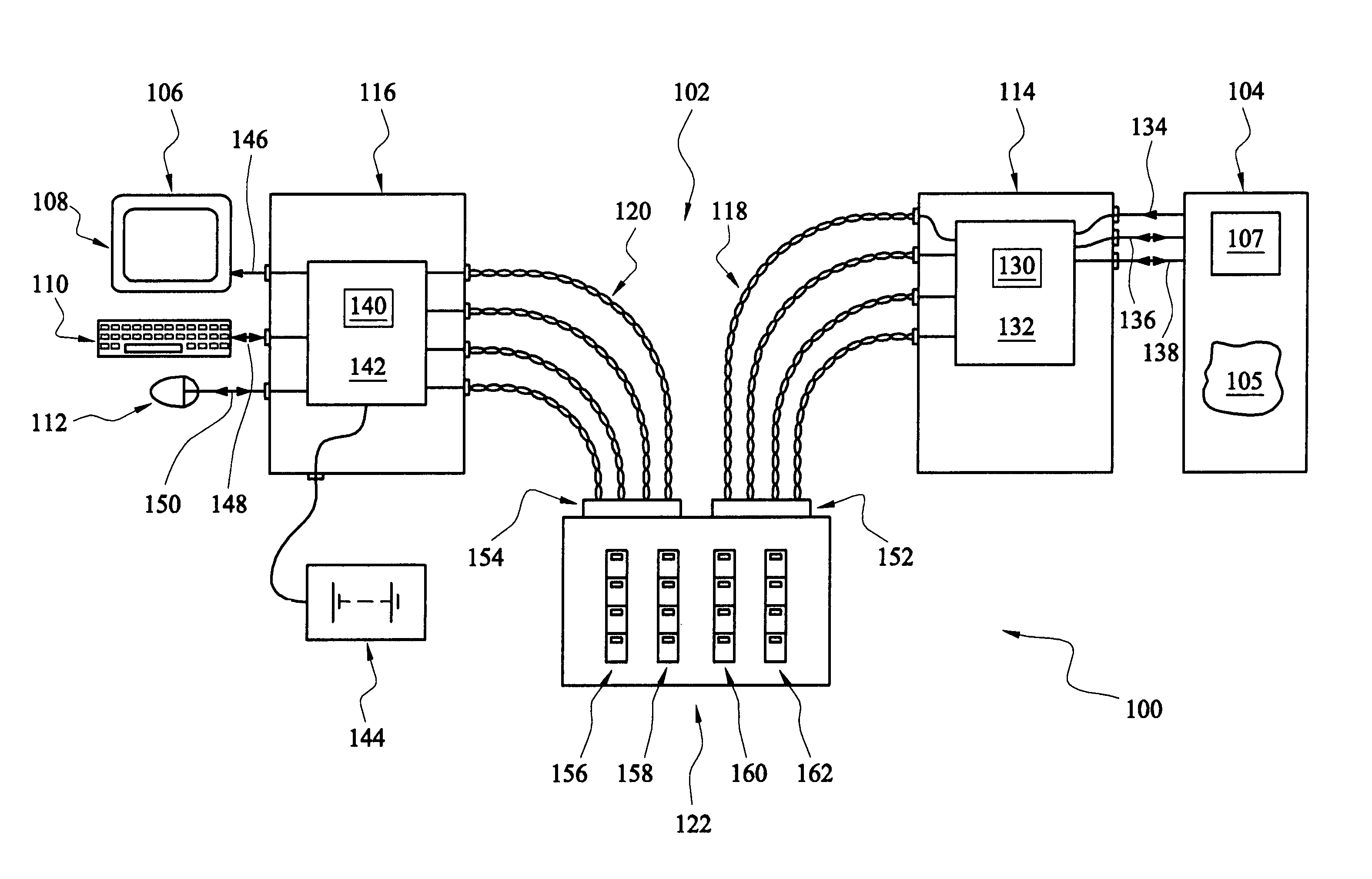
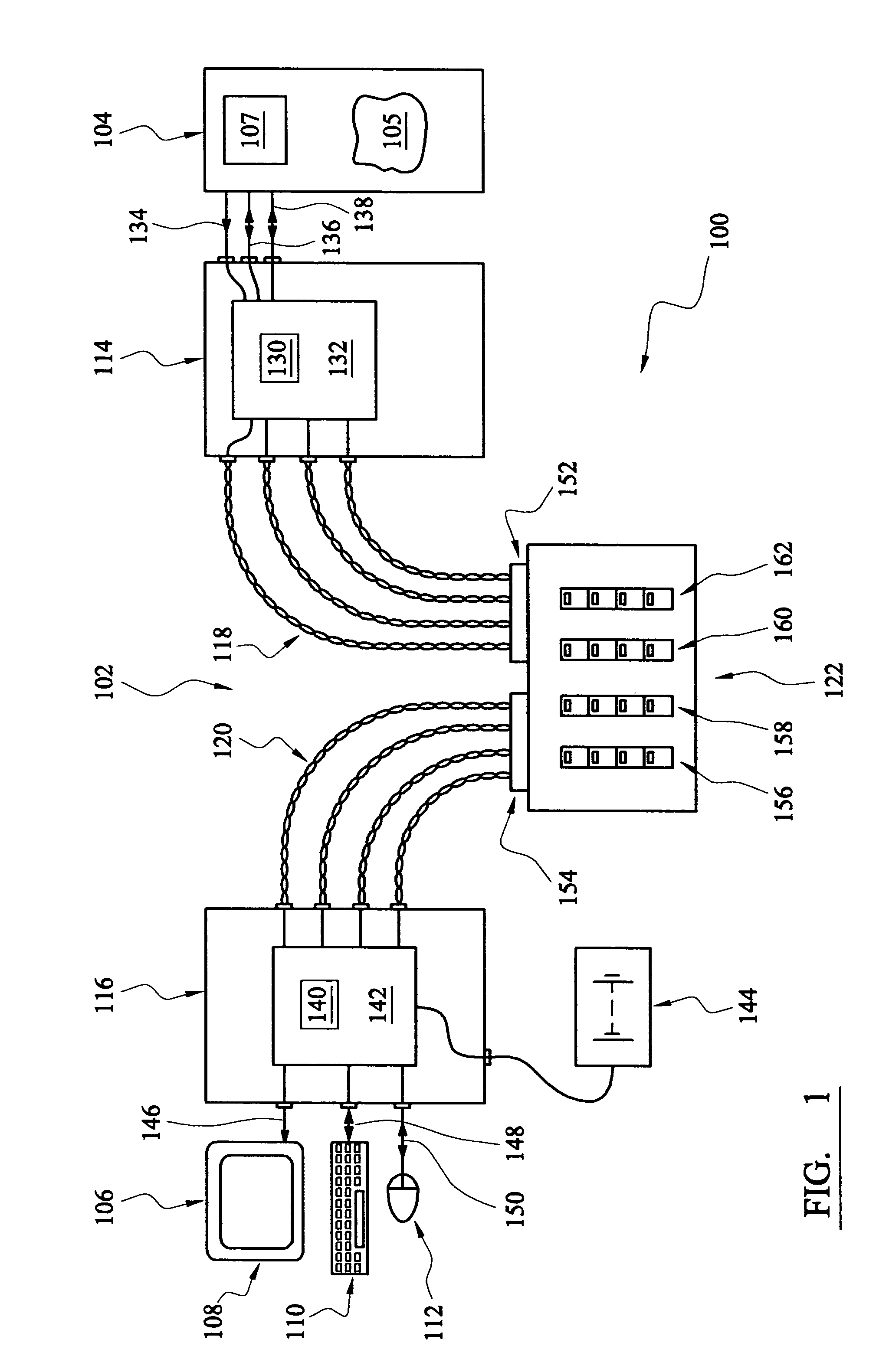
[0037]With reference to FIG. 1, there is shown a computer system 100 including a KVM extender 102 connecting a computer 104 executing software 105 to a KVM console 106 including a monitor 108, keyboard 110 and mouse 112. KVM extender 102 includes a local unit 114 and a remote unit 116 connected by a four twisted pair cable 118, 120 via a video signal skew compensation device 122.

[0038]Local unit 114 includes a microprocessor 130 controlling various signal processing and routing devices 132 as will be described in greater detail below. Respective video 134, keyboard 136 and mouse 138 cables connect the video, keyboard and mouse ports of the computer 104 to connectors of the local unit by which video signals are supplied to the remote unit and keyboard and mouse signals are transmitted between the remote unit and computer. The video signal comprises red, green and blue colour signals and vertical and horizontal synchronisation signals.

[0039]Remote unit 116 includes a microprocessor 14...


PUM


Abstract

Devices for reducing and determining the skew between colour video signals transmitted over at least two different video cables are described. A KVM extender including such devices is also described. The skew reduction device includes a plurality of video signal transmission tracks selectably connectable to each of the video cables to increase the video signal transmission path length so as to more closely matching the total video signal path length for each of the colour video signals. The skew determination device comprises a processing device, a signal generator for applying measuring signals to each of the video signal cables and signal detection circuitry to receive measuring signals transmitted over the video signal cables. Detection signals are output to the processing device which is programmed to determine an indication of the transmission path length difference between the video signal cables.

Description

BACKGROUND OF THE INVENTION[0001]The present invention relates to video signal skew, and in particular to devices and methods for determining and compensating for skew between video signals transmitted over wires.[0002]When video colour signals are separately transmitted over wires of different lengths, then the signals become temporally separated (skewed) which degrades the image generated by a video display device. This can particularly be a problem in a class of devices known as KVM (Keyboard, Video monitor and Mouse) extenders. These devices allow a KVM console to be used to control a distant computer over distances of several hundred metres.[0003]Such devices often use twisted pair cabling to transfer video signals from the computer to the monitor, and data and control signals between the computer and mouse and keyboard. However, twisted pair cables are more suited to carrying high speed digital signals, rather than analogue video signals. Different pairs of cables have differe...

Claims


Application Information

Patent Timeline
IPC IPC(8): G09G5/10G06F3/023H04B3/40H04N7/10H04N9/64H04N17/00H05K1/00H05K1/02
CPCG06F3/023H04B3/40H04N7/108H05K1/0248H05K2201/09263H04N17/00H05K1/0298H04N9/64
Inventor DICKENS, NIGEL ANTHONYDICKENS, ADRIAN CHRISTOPHERSTEEL, DARRIN
Owner ADDER TECHNOLOGY
Learn More