Carbon heat-treatment process

a heat treatment process and carbon technology, applied in the field of activated carbon thermal production, can solve the problems of temperature spike and product quality reduction, and achieve the effects of reducing capital cost requirements, easy adjustment, and precise repeatability

Active Publication Date: 2012-11-13
PNEUMATIC PROCESSING TECH
View PDF64 Cites 27 Cited by
  • Summary
  • Abstract
  • Description
  • Claims
  • Application Information

AI Technical Summary

Benefits of technology

[0025]5. Another key factor is the need to prevent carbonaceous feed particulates from undergoing adverse reaction conditions such as overheating and / or favoring partial combustion reactions thereby affecting the yield and pore structure. The process must also be able to retain the coarser feed material longer than the finer material. This can all be accomplished by the cyclonic flow pattern within the Reactor created by the injection of carbonaceous feed either mechanically or pneumatically and using a conveying gas and / or the injection of second gas such as re-circulated flue gases or steam to create a cyclonic material flow pattern. Cyclonic gas flow rotational velocities within the Reactor should be a minimum of 90 RPM average velocity and more ideally in the 120 to 240 RPM range. Cyclonic flow in the Reactor in conjunction with the feed conveying gas and or secondary gas composition creates a more uniform AC product by buffering the carbonaceous feed from excessive Reaction Vessel temperatures caused by the burner flame and / or from excessive partial combustion of the feed. By utilizing this method, adverse carbon particle surface reactions, ash fusion, excessive gasification and product loss is avoided. In addition cyclonic flow in the Reactor increases particulate retention time by creating a helical material flow pattern thereby increasing the particle path length.
[0026]6. Pneumatic conveying carbon feedstock into a flash activation Reaction Vessel utilizing a mixture of a conveying gas and a second gas. This results in the ability to control the Reaction Vessel flow profile in which devolatilization and activation predominately occurs in distinct regions of the Reaction Vessel. By controlling the rate of addition, moisture percentage, and / or activation content of a second gas independently of the conveying gas, the reaction time, temperature, oxidizing and reducing conditions, and other aspects of the devolatilization and activation process stages can be controlled using a single or multiple vessels. Alternatively carbonaceous feedstock can be introduced into the Reaction Vessel using mechanical conveying and immediately thereafter mixed with a air / gas source with the desired composition and volume within the Reaction Vessel. The air / gas source can be concurrently introduce with the feed material or injected previous to the material feed. This would enable the creation of substantially similar material flow conditions within the Reaction Vessel achievable with pneumatic conveying.
[0030]10. The design of the Reaction Vessel, which again is defined as the vessel(s) from carbonaceous feed injection through to the product disengagement and separation from reaction gases, must create an oxidizing environment transitioning to a reducing environment. For many precursor materials the initial oxidizing environment prior to transitioning to a reducing environment can be beneficial as a pretreatment of the feed material surface area immediately prior to activation as an additional means to control adverse reactions. When utilizing Single Stage Activated Carbon Production in a single Reaction Vessel, devolatilization occurs in an oxidizing transitioning to a reducing environment and the activation occurs in primarily a reducing gas environment. To assist in creating distinct regions additional gases such as air, re-circulated flue gas, and / or moisture can be added at various points along the gaseous flow path of the Reaction Vessel thereby creating distinct reaction zones within the Reaction Vessel. When utilizing Dual Stage Activated Carbon Production in multiple Reaction Vessels, activation occurs in an oxidizing transitioning to a reducing environment in a single Reaction Vessel. The devolatilization occurs in primarily a reducing gas environment in a separate Reaction Vessel which utilizes the separated flue gases from the first Reaction Vessel as the heat source. To assist in creating distinct regions when utilizing Dual Stage Activated Carbon Production additional gases such as air, re-circulated flue gas, and / or moisture can be added at various points along the gaseous flow path of either or both of the Reaction Vessels.
[0032]12. Moreover, by including a co-product industrial mineral to be calcined, such as magnesium, trona, or calcium carbonate, a calcination product (e.g., lime) can be produced simultaneously with the activated carbon and can further be a source of temperature control due to the endothermic nature of calcination. The co-produced or co-product industrial minerals are defined as minerals that are capable of undergoing calcination under the same operating conditions as the carbon being heat treated and that represents at least 50% of the heat-treatment system output in terms of quantity. So, for example, limestone is introduced with the carbon being heat treated in sufficient quantity that it results in at least 50% of the output (in the form of lime) in addition to activated char. Thus, co-product industrial minerals are to be distinguished from mere “enhancers,” which are added to the system but do not result in a separate “co-product” in any appreciable amounts (and certainly not over 50% of the system output of products). For example, adding a bromide dopant to the carbon would be considered a an enhancer and not a co-product industrial mineral because mainly brominated carbon results, with no other “co-product” making up at least 50% of the system output of products. Of course, the co-product industrial minerals can add to the effectiveness of the AC. For example the removal of sulfur in coal power plant flue gases with lime can benefit the ability of AC to adsorb mercury. Another example is the industrial mineral commonly referred to as trona where when co-calcined with AC can benefit the mercury adsorption by not only removing sulfur compounds but by also adsorbing mercury in the trona pore structure created during calcination.
[0034]14. Furthermore, this method of AC production lends itself to pre-activation halide compound treatments, such as bromination. This treatment can occur in several ways such as the premixing of halide salts such as sodium bromide, calcium bromine or iron bromide or a combination of halides with the carbon precursor material resulting in the concurrent activation and halide treatment of the AC. Due to the thermal treatment conditions, the concurrent activation and halogenation of the carbon precursor can have a positive impact on the effectiveness of the halogenation of the activated carbon.
[0036]Overall there is a need for a process that can significantly reduce the capital cost requirements for AC production and processing and that is inherently stable, easily adjustable, and precisely repeatable.

Problems solved by technology

In most cases the finer feed will experience excessive activation or gasification resulting in product loss while the more granular feed will experience a lesser degree of activation leading to a reduction in product quality.
On start up the temperature spike is caused by excessive carbonaceous feed combustion until excess oxygen is depleted.

Method used


Image

  • Carbon heat-treatment process
  • Carbon heat-treatment process
  • Carbon heat-treatment process

Examples


Embodiment Construction

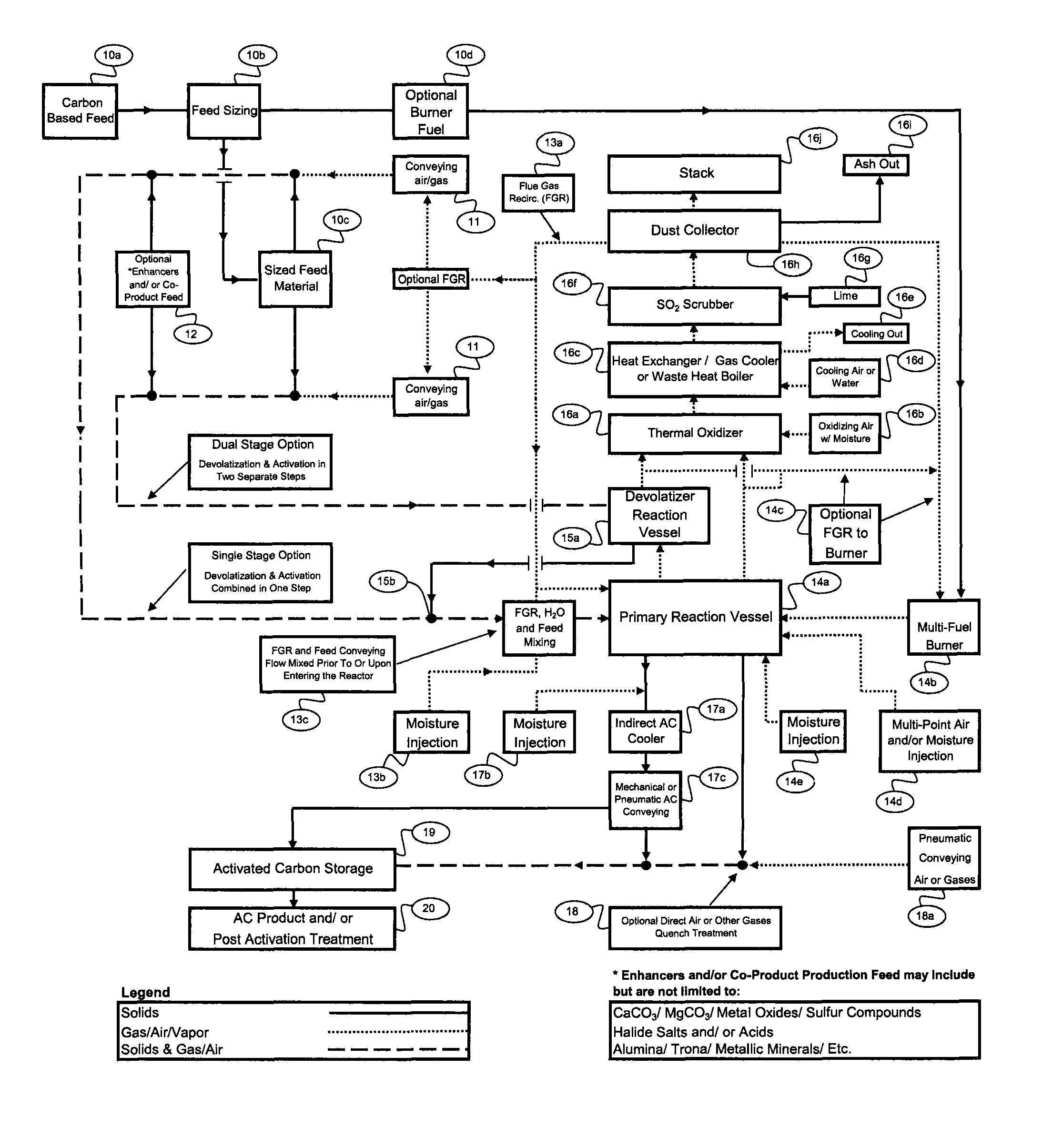
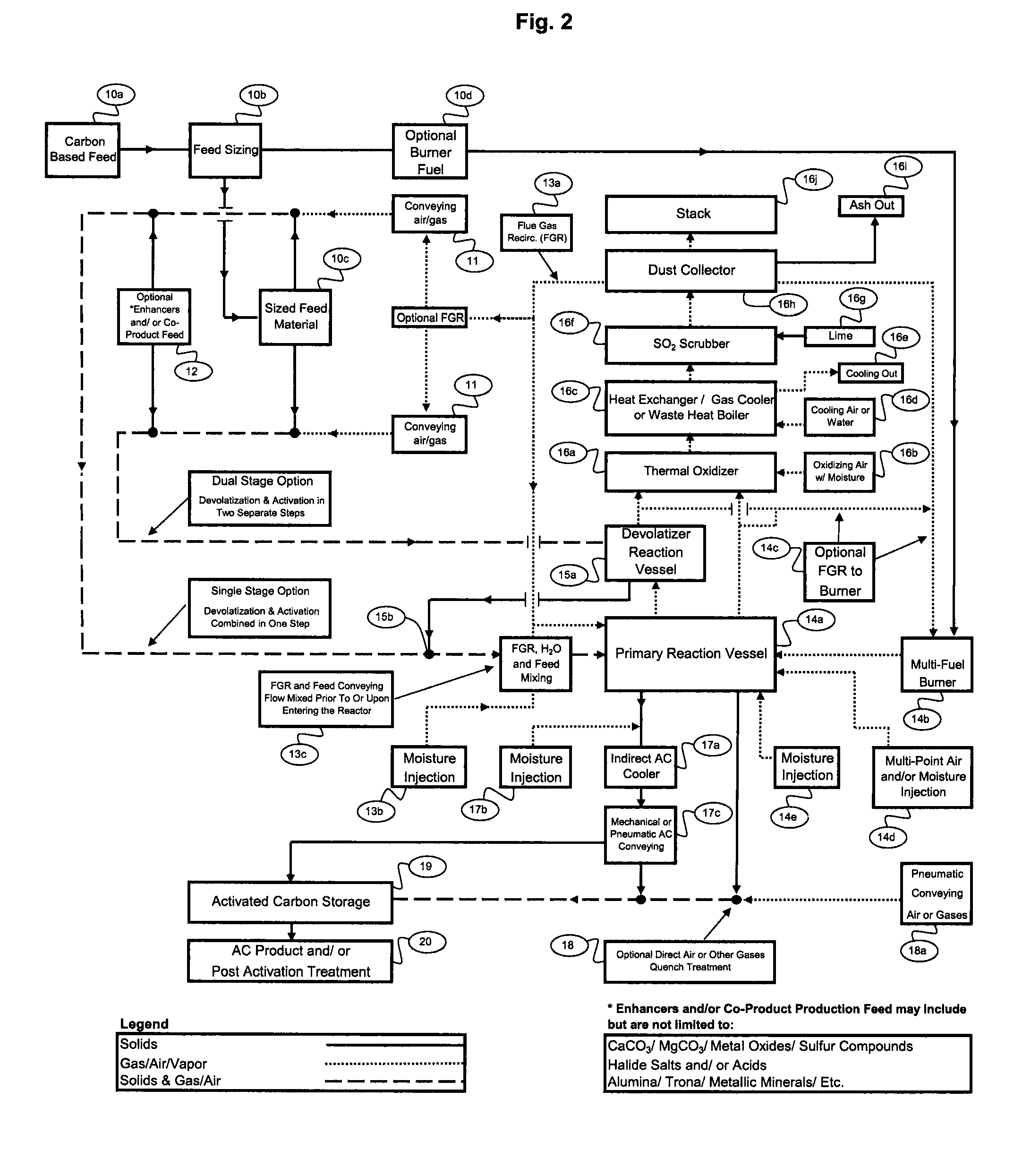
[0042]Processes according to the invention can be divided into the following main categories: 1) Carbonaceous feed material (feedstock) preparation, 2) Calcination or other heat treatment, 3) Activation, 4) Post activation treatment, 5) Process gas conditioning, and 6) Optional AC enhancement practices. The calcining stage can accomplish both devolatilization and subsequent activation reactions of carbonaceous feed material in a single Reaction Vessel (Single-Stage Activated Carbon Production) or in two separate Reaction Vessels (Dual-Stage Activated Carbon Production). Each of the following sections corresponds to the Process Block Flow Diagram of FIG. 2 (with the same numbers indicating like parts / processes in FIGS. 3-4).

Carbonaceous Feed Material Preparation 10a-10d

[0043]A first embodiment of the invention can produce a combination of granular and pulverized AC utilizing a variety carbonaceous feed stock material. A blend of carbonaceous materials can also be created to tailor t...


PUM

PropertyMeasurementUnit
sizeaaaaaaaaaa
retention timeaaaaaaaaaa
surface areaaaaaaaaaaa

Abstract

Methods for producing devolatilized and / or activated carbon in a reactor or reaction vessel of a heat treatment system from a suitable carbonaceous feedstock by introducing the feedstock into the reactor tangentially at a rotational velocity of at least 90 RPM. The methods include the steps of providing a combination of conveying means and a gas flow having various compositions and creating distinct carbonaceous feedstock material flow patterns and process conditions such that the feedstock is conveyed through the reactor or reaction vessel and heated via combustion, thereby producing activated carbon or other heat-treated carbons while concurrently avoiding adverse reaction conditions. Single and two-stage heat treatment systems may be used to heat a carbon feedstock, to which one or more industrial minerals may be added to co-produce compositions such as lime with the heat-treated carbon.

Description

BACKGROUND OF THE INVENTION[0001]1. Field of the Invention[0002]The invention relates to the thermal production of activated carbon and other heat-treated carbons.[0003]2. Description of the Related Art[0004]Recent environmental awareness has focused on the need to remove harmful mercury emissions from coal fired power plants. These efforts have led to several developments with regards to effective mercury removal techniques. The most successful method for mercury removal utilizes pulverized activated carbon injected into the flue gas stream of a coal fired power plant. Extensive research in this field has demonstrated that not all activated carbons effectively remove mercury. There are many factors that influence mercury removal effectiveness using activated carbon in coal fired power plants such as coal fuel type, mercury concentrations, etc. One of the largest factors in the ability of activated carbon to adsorb mercury is the activated carbon pore structure. Not all activated ca...

Claims


Application Information

Patent Timeline
Patent Type & Authority Patents(United States)
IPC IPC(8): C01B31/08B01J19/00C09C1/56C01B32/336
CPCC01B31/08C01B32/30C01B32/312
Inventor JONES, MICHAEL A.
Owner PNEUMATIC PROCESSING TECH
Why Eureka
Try Eureka