System for Transmitting and Receiving Video Digital Signals for Links of the "LVDS" Type

a technology of video digital signals and transmission systems, applied in the field of digital links of the type lvds, can solve problems such as inability to improve a system, link is totally incompatible, and transmission errors can occur

Inactive Publication Date: 2012-03-01
THALES SA
View PDF6 Cites 4 Cited by
  • Summary
  • Abstract
  • Description
  • Claims
  • Application Information

AI Technical Summary

Benefits of technology

[0022]the transmission system comprises a means making it possible

Problems solved by technology

When the link is more than a few metres long, depending on the features of the multiple-pair cable, transmission errors can occur due to the skew between the various channels which increases with length.
Unfortunately the “TMDS” link is totally incompatible with the “LVDS” link, their respective interfaces not being able to communicate wit

Method used


Image

  • System for Transmitting and Receiving Video Digital Signals for Links of the "LVDS" Type
  • System for Transmitting and Receiving Video Digital Signals for Links of the "LVDS" Type
  • System for Transmitting and Receiving Video Digital Signals for Links of the "LVDS" Type

Examples


first embodiment

[0071]A first embodiment consists in carrying out a small tattooing operation on the image, an operation known as “watermarking” housed in a corner of the image, at the top left for example. The tattoo is of low intensity using the least significant bits or “LSB” of the pixels of the image. It is possible, for example, to use the colour bits G0 and B0. This tattoo is not visually perceptible because of its location and its low visual impact. But this type of function is not a priori easy to carry out with an application software programme in the case of an item of equipment based on a card for a microcomputer of the PC type.

second embodiment

[0072]A second embodiment consists in introducing a recognition graphic pattern of the “post-it” type. In this case, the graphic pattern must be superimposed on the image at any application executed by the transmitting equipment. This means that it is necessary to generate a “patch” of image that always replaces the original video image. The method making it possible to generate this pattern is similar to that of the small software program called a “post-it” having the “always on top” parameter enabled. In our application, the major difference compared with the “post-it” software program is that the location of this image fraction must be absolutely fixed and impossible to move. The height of the pattern may be only one line, preferably at the left on the top line of the screen.

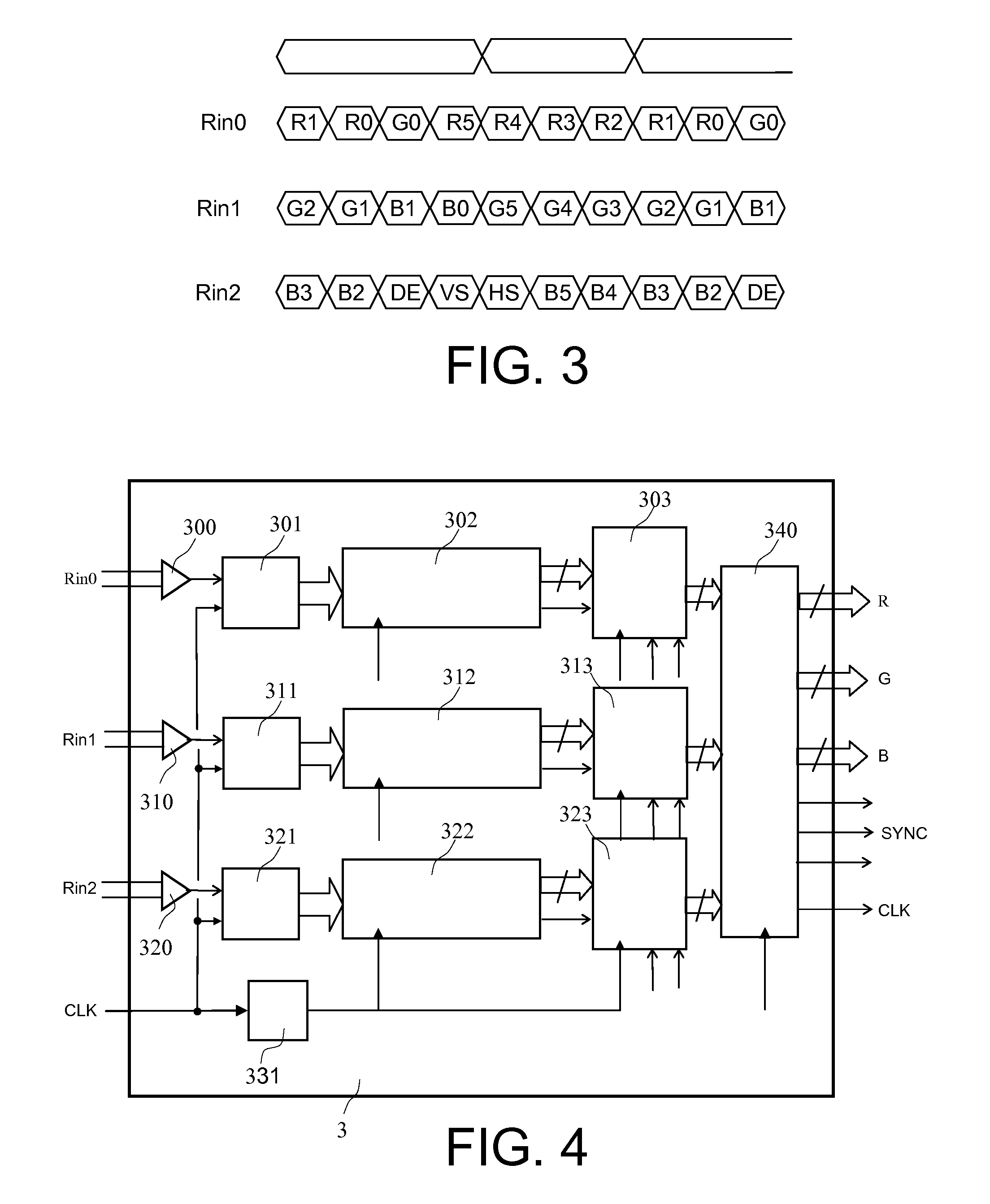
[0073]The synchronization of the Rin1 and Rin0 channels is based on the recognition of this graphic pattern. Naturally the detection is validated in a time window relative to the synchronization information t...


PUM


Abstract

Systems for transmitting and receiving signals of video digital images for links of the “LVDS” type comprise a transmit module, a transmission link and a receive module. The “RGB” video signal comprises the colour and synchronization signals and a clock signal. The “LVDS” video signal transmitted via the transmission link comprises several primary signals, the first primary signal dedicated to the clock signal, the second primary signal comprising the synchronization information, the other primary signals comprising only the colour encoding information. The function of the “LVDS” transmit module is to encode the “RGB” video signal into an “LVDS” video signal and the function of the receive module is to decode the “LVDS” signal into an “RGB” signal. The system comprises the following particular arrangements: the transmission system having a means making it possible to inlay a graphic recognition pattern in the “RGB” video signal; the receive means operating in oversampling and having a test means capable of identifying the synchronization information and the graphic recognition pattern.

Description

CROSS-REFERENCE TO RELATED APPLICATION[0001]This application claims priority to foreign French patent application No. FR 1003435, filed on Aug. 24, 2010, the disclosure of which is incorporated by reference in its entirety.FIELD OF THE INVENTION[0002]The field of the invention is that of digital links of the “LVDS” type, the acronym meaning “Low Voltage Differential Signalling”. The invention relates more particularly to the system for transmitting and receiving transmitted signals and their encoding. The invention may apply to any field using “LVDS” interfaces to transmit video information. However, it is primarily designed for aeronautical applications.BACKGROUND[0003]These links are usually used for the transmission of images and have different names. The most widespread are: “FPD-LINK”, “Camera-Link”, “Channel-Link”, “FLATLINK”, etc. As an example, FIG. 1 represents a complete transmission system of the “LVDS” type. It comprises a transmission interface 1, the transmission line ...

Claims


Application Information

Patent Timeline
IPC IPC(8): H04N11/06
CPCG09G5/006G09G5/008G09G2380/12G09G2340/12G09G2370/14G09G2330/12H04N7/24
Inventor SONTAG, YVESGUFFROY, MICHAEL
Owner THALES SA
Why Eureka
Try Eureka