Lighting and/or signalling device with a moveable daytime element

a signalling device and daytime element technology, applied in the direction of lighting support devices, lighting and heating devices, transportation and packaging, etc., can solve the problems of requiring a lot of space, unable to install such a daytime lighting device, and unable to use the headlamp intended for night-time use to provide the daytime lighting function

Inactive Publication Date: 2012-03-01
VALEO VISION SA
View PDF2 Cites 13 Cited by
  • Summary
  • Abstract
  • Description
  • Claims
  • Application Information

AI Technical Summary

Benefits of technology

[0011]The object of the present invention is therefore to obviate the drawbacks described above, mainly by integrating the daytime lighting function with a lighting or signalling element of the vehicle, so as to allow it to be seen during the day while also making it possible for it to cede its place to conventional lighting under night-time conditions.

Problems solved by technology

One drawback of this type of daytime-specific lighting device is that it requires a lot of space.
Specifically, certain vehicles such as, for example, sports cars, have peculiarly shaped front bumpers, with sharp edges, on which it is impossible to install such a daytime lighting device while respecting the standard mentioned above.
In such a case it is impossible to use the headlamp intended for night-time use to provide the daytime lighting function because it would mean keeping these optical systems open constantly, whatever the conditions of use of the vehicle.
This evidently runs contrary to the retractable function of this optical system and negates the aerodynamic and aesthetic advantages desired by manufacturers.
Moreover, manufacturers of these sports vehicles wish to ensure that their vehicles have an attractive outline that is as uncluttered as possible whereas such a daytime lighting device is liable to be detrimental to this attractive outline.
Finally, providing the space to install this daytime lighting device in the bumper requires additional design and production time on the part of the manufacturers of these bumpers.

Method used


Image

  • Lighting and/or signalling device with a moveable daytime element
  • Lighting and/or signalling device with a moveable daytime element
  • Lighting and/or signalling device with a moveable daytime element

Examples


Embodiment Construction

[0042]It should be noted that the figures show the invention in detail so as to demonstrate the invention, the figures may of course be used to better define the invention if required.

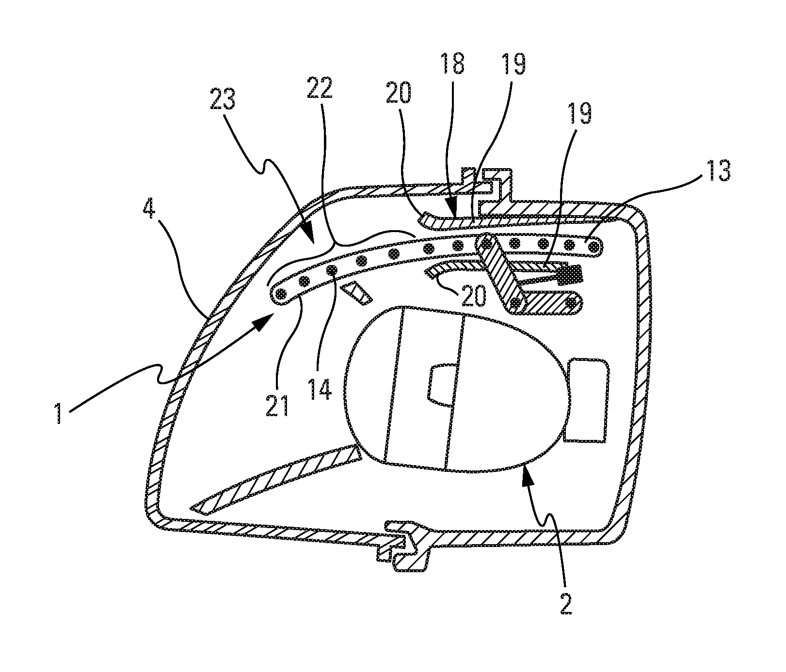
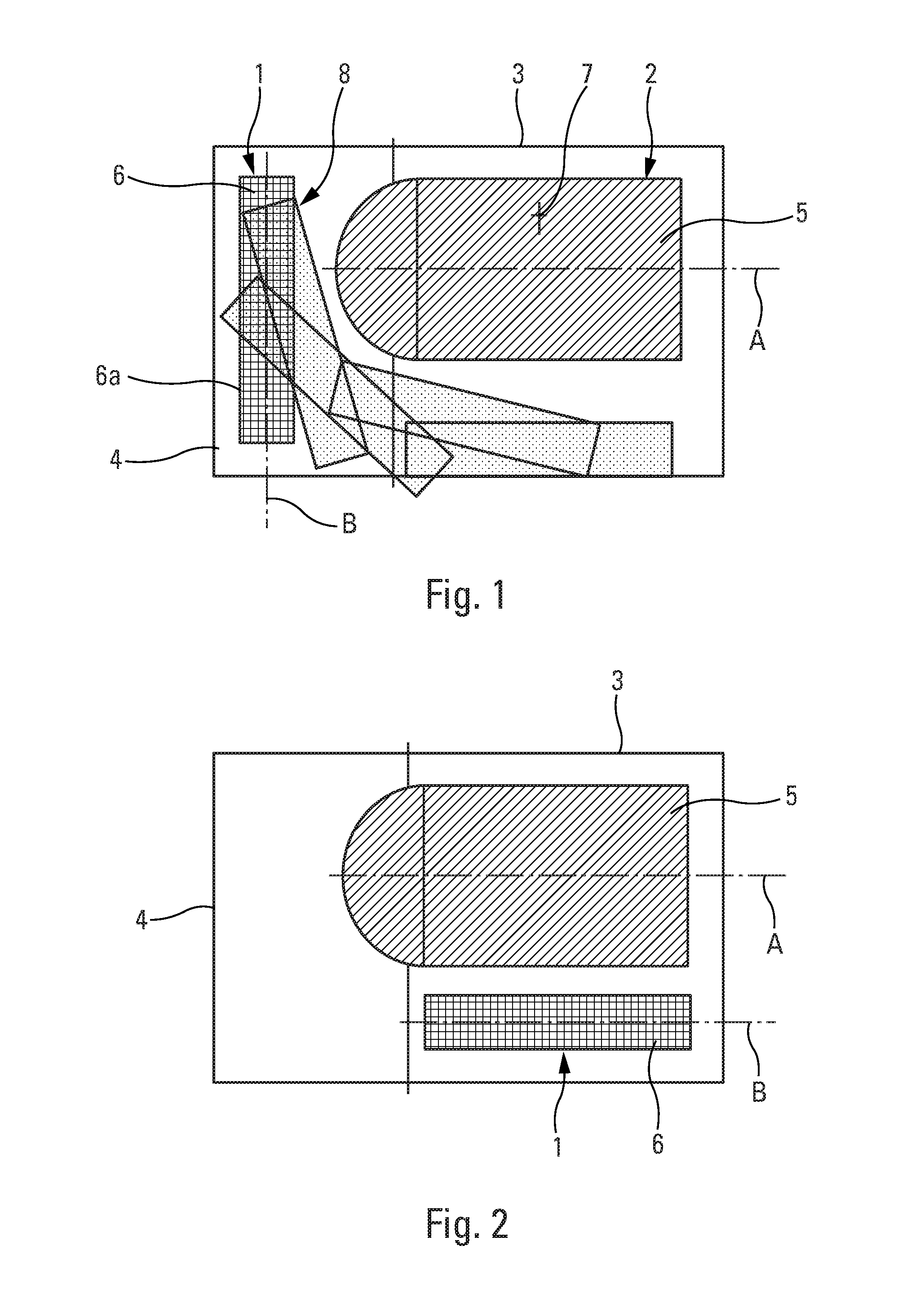
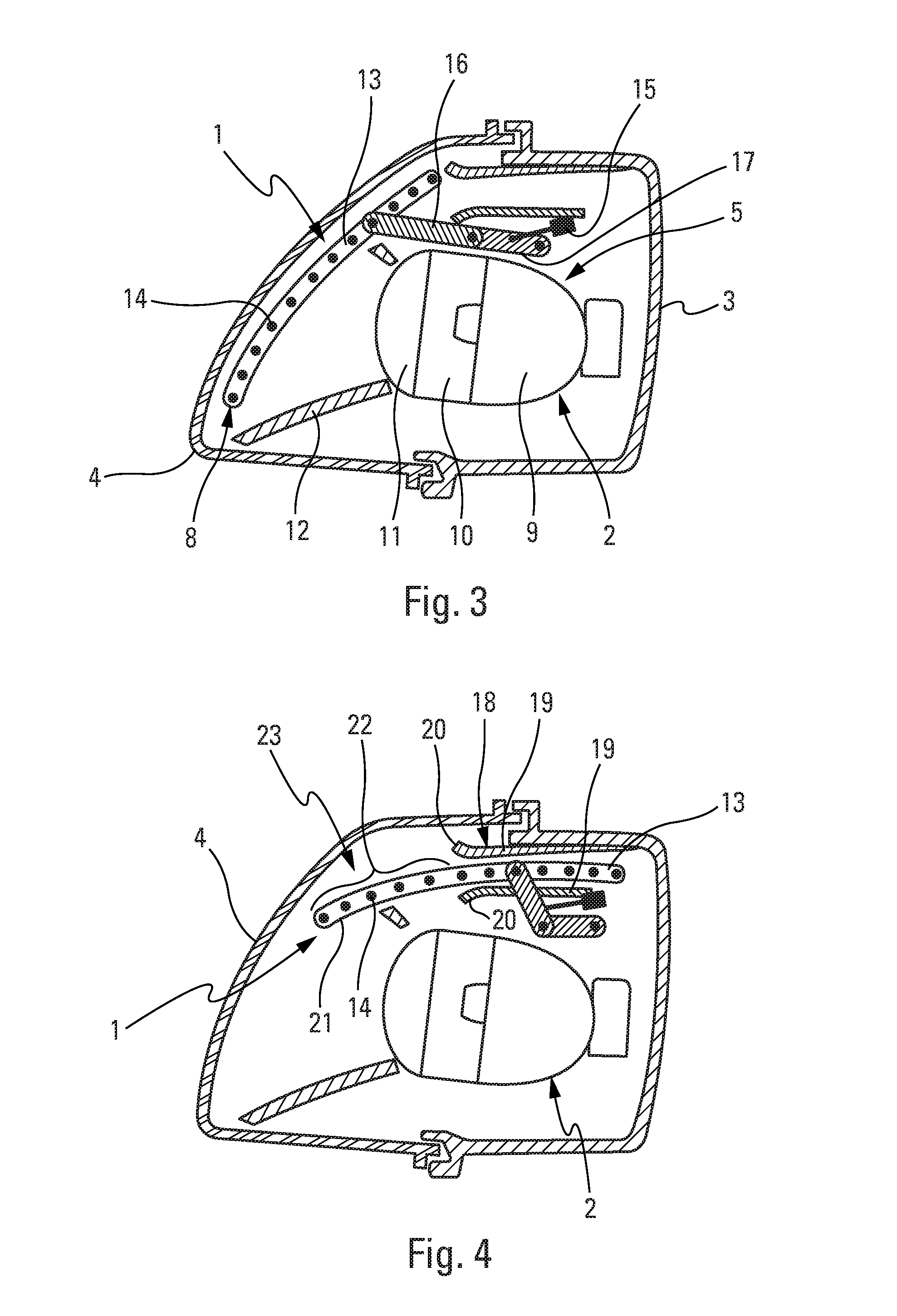
[0043]FIG. 1 illustrates schematically the lighting and / or signalling device as seen from above, under daytime conditions. This device is designed to be installed on the front part of the vehicle so as to deliver a light beam. It comprises at least two photometric functions 1 and 2. The first photometric function 1 is a daytime lighting device, i.e., a device that is employed during the day. The second photometric function 2 is a night-time lighting device, i.e., a device that is employed when the ambient lighting level passes below a certain threshold. The activation or operation of this second photometric function is controlled by the user of the vehicle via a switch or automatically by means of a light detector installed on the vehicle.

[0044]The device according to the invention comprises a housing ...


PUM


Abstract

A lighting and/or signalling device arranged so as to provide at least a first photometric function and a second photometric function, wherein the device comprises at least one moveable element on which at least the first photometric function is installed and the movement of which is subject to the operation of the second photometric function.

Description

CROSS-REFERENCE TO RELATED APPLICATIONS[0001]This application claims priority to French Application No. 1056875 filed Aug. 31, 2010, which application is incorporated herein by reference and made a part hereof.BACKGROUND OF THE INVENTION[0002]1. Field of the Invention[0003]The technical field of the present invention is that of lighting and / or signalling devices for automotive vehicles.[0004]2. Description of the Related Art[0005]A new lighting function has appeared recently on automotive vehicles. It is lighting that is switched on during the daytime. This function is ensured either by switching on a headlamp that is normally reserved for night-time use, or by installing a specific lighting device mounted on the front bumper of the vehicle.[0006]In this second case, the daytime lighting device must meet a standard concerning the location on the vehicle and the power of the light beam of the daytime lighting device.[0007]One drawback of this type of daytime-specific lighting device ...

Claims


Application Information

Patent Timeline
Patent Type & Authority Applications(United States)
IPC IPC(8): B60Q1/08B60Q1/00F21W107/10
CPCB60Q1/0041B60Q1/05B60Q1/2607B60Q2400/30F21S48/236F21S48/2243F21S48/2268F21S48/2281F21S48/215F21S43/14F21S43/239F21S43/245F21S43/249F21S43/315B60Q1/2692
Inventor BAKACHA, MALIKPUENTE, JEAN-CLAUDEALBOU, PIERRE
Owner VALEO VISION SA
Why Eureka
Try Eureka