
Radiographic image capturing system and radiographic image capturing method

a radiographic image and imaging system technology, applied in the direction of material analysis using wave/particle radiation, instruments, applications, etc., can solve the problems of field-emission radiation sources that cannot capture radiation images, small and lightweight, and difficulty in preparing an appropriate external power supply, etc., to achieve the effect of easy expansion of the radiation radiation rang

Active Publication Date: 2012-03-01
FUJIFILM CORP
View PDF1 Cites 28 Cited by
  • Summary
  • Abstract
  • Description
  • Claims
  • Application Information

AI Technical Summary

Benefits of technology

[0009]As long as a subject is irradiated with an optimum dose (exposure dose) of radiation depending on the subject, a radiographic image of the subject can be captured based on an exposure dose that is large enough for a doctor to read the resultant radiation image correctly, and the subject remains free of undue radiation exposure.
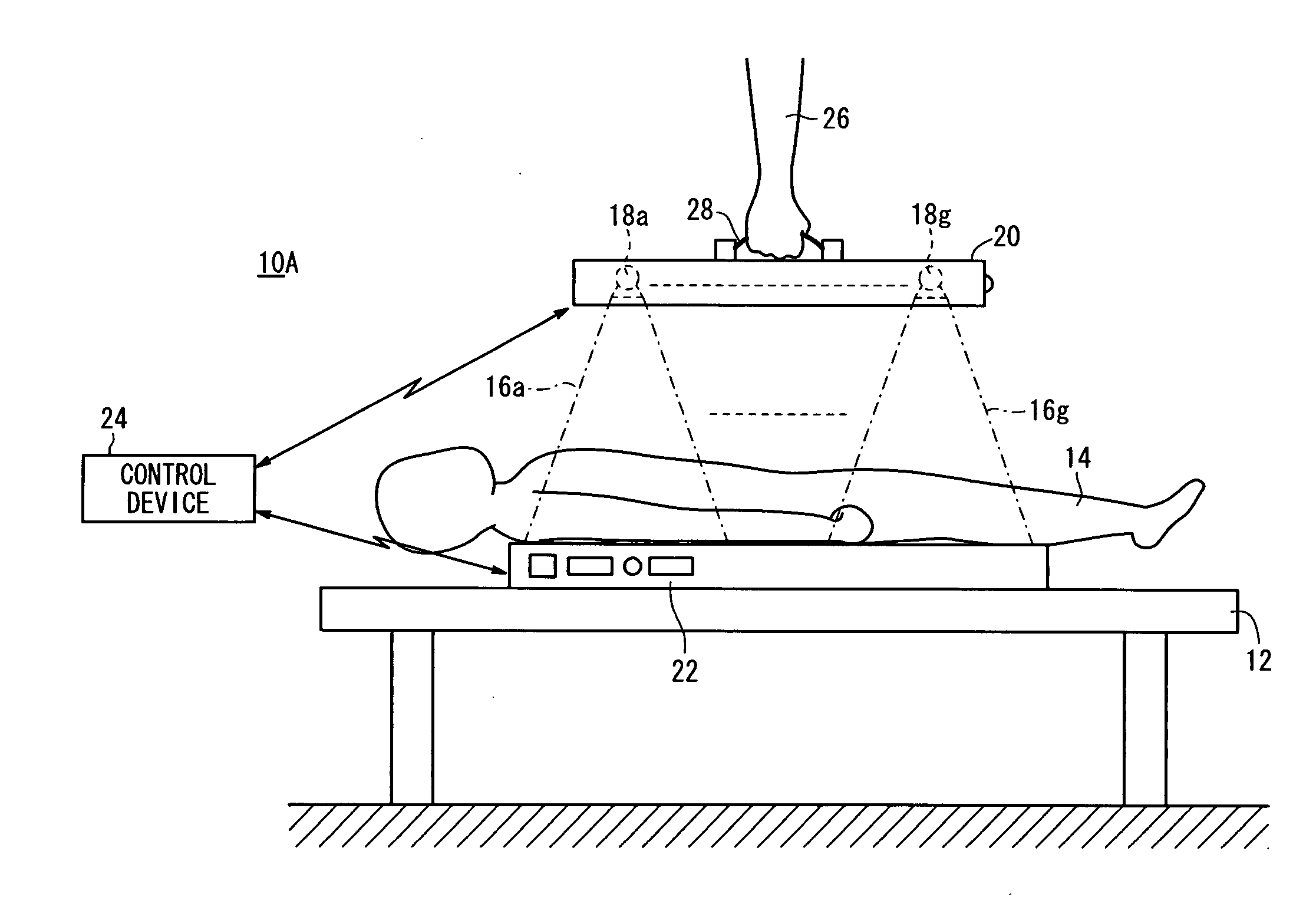
[0040]As described above, in the third invention, an irradiation range of the radiation is not set simply by enabling a desired irradiation range (region to be imaged of the subject) to be covered, but rather, radiation doses of the respective radiation emitted from the radiation sources during the second image capturing process are weighted based on the first radiographic image. Accordingly, even if the first and second image capturing processes are carried out with respect to the subject using field-emission radiation sources, the irradiation range of the radiation can easily be enlarged, and radiation can be applied at an optimum radiation dose (exposure dose) with respect to the subject.

Problems solved by technology

If a field-emission radiation source is operated at a site, it is highly likely that difficulties will be experienced in preparing an appropriate external power supply.
However, a battery-powered field-emission radiation source, although it is small and lightweight, emits a small dose of radiation.
Because of the small irradiation range, and also due to the small dose (exposure dose) of radiation applied to the subject, the field-emission radiation source may fail to capture a radiation image based on an exposure dose that is sufficiently large for a doctor to read radiation images correctly.
However, as noted above, if a field-emission radiation source simply applies radiation to a subject in order to cover a desired irradiation range, the subject may not necessarily be irradiated with an optimum dose of radiation.

Method used


Image

  • Radiographic image capturing system and radiographic image capturing method
  • Radiographic image capturing system and radiographic image capturing method
  • Radiographic image capturing system and radiographic image capturing method

Examples


first embodiment

[Modifications of First Embodiment]

[0211]Modifications (first through sixth modifications) of the first embodiment will be described below with reference to FIGS. 12A through 18B.

[0212]Parts of such modifications, which are identical to those shown in FIGS. 1 through 11, are denoted by identical reference characters, and such features will not be described in detail below.

first modification

[First Modification]

[0213]In the first modification, as shown in FIGS. 12A and 12B, each of three groups 54, 56, 58 contains one radiation source 18a through 18c. In this case, the geometric center position in the three radiation sources 18a through 18c is the position of the central radiation source 18b. The central group 56 includes the geometric center position, whereas the other groups 54, 58 are positioned at both sides of the geometric center position.

[0214]According to the first modification, in an image capturing process with respect to a chest region as shown in FIG. 12A, weighting of the doses is carried out such that the doses of radiation 16a, 16c emitted from the radiation sources 18a, 18c included in the groups 54, 58 are of a maximum dose level, whereas the dose of radiation 16b emitted from the radiation source 18b included in the group 56 is of a lower dose level. On the other hand, in an image capturing process with respect to a hand as shown in FIG. 12B, weighting...

second modification

[Second Modification]

[0216]In the second modification, as shown in FIGS. 13A and 13B, each of four groups 156, 158, 160, 162 contains one radiation source 18a through 18d. In this case, the geometric center position in the four radiation sources 18a through 18d is an intermediate position between the radiation source 18b and the radiation source 18c. The groups 158, 160 including the radiation sources 18b, 18c do not include the geometric center position but are positioned near the geometric center position, whereas the other groups 156, 162 are positioned at both sides of the geometric center position.

[0217]According to the second modification, in an image capturing process with respect to a chest region as shown in FIG. 13A, weighting of the doses is carried out such that the doses of radiation 16a, 16d emitted from the radiation sources 18a, 18d included in the groups 156, 162 are of a maximum dose level whereas the doses of radiation 16b, 16c emitted from the radiation sources 1...


PUM


Abstract

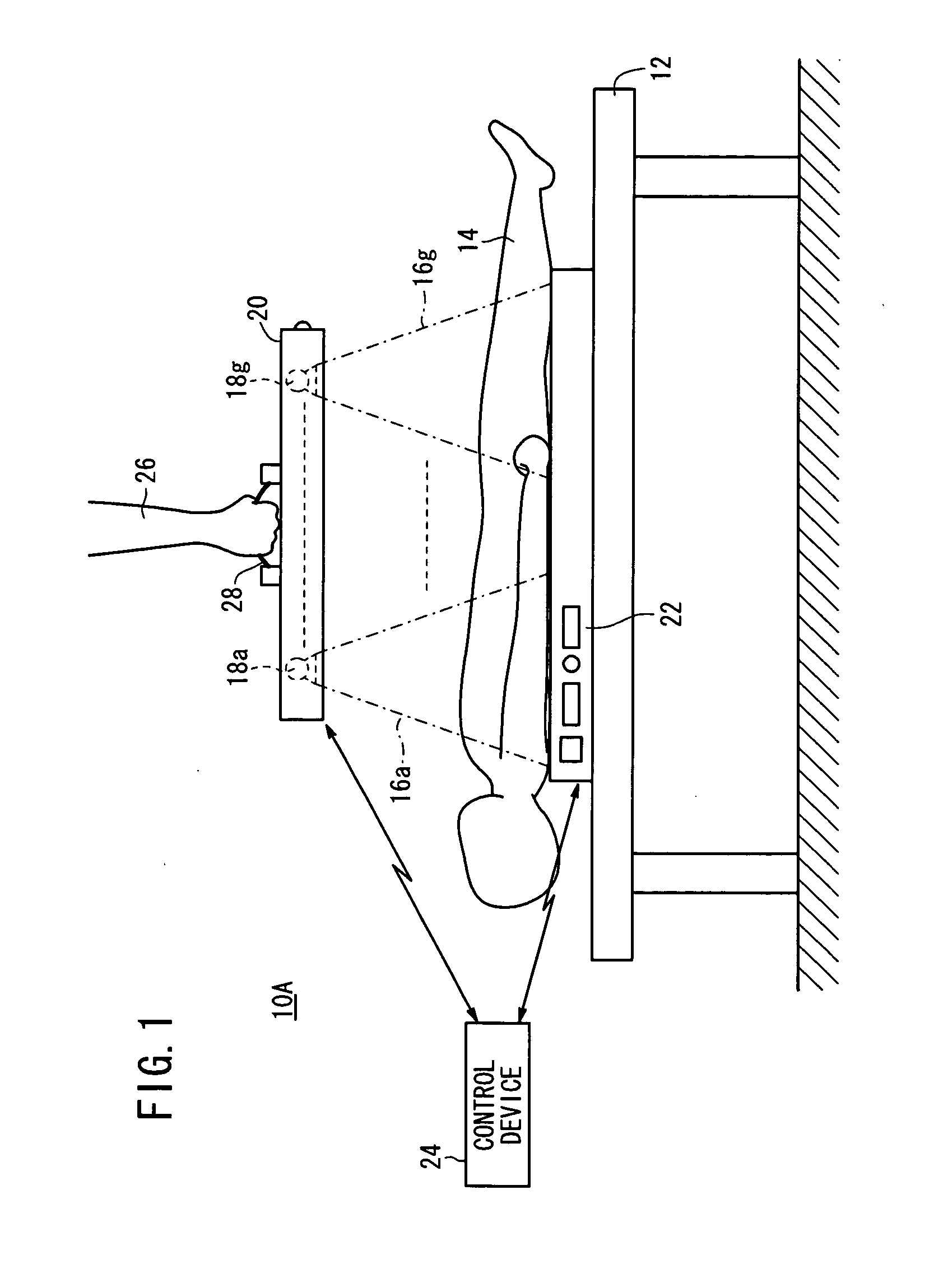
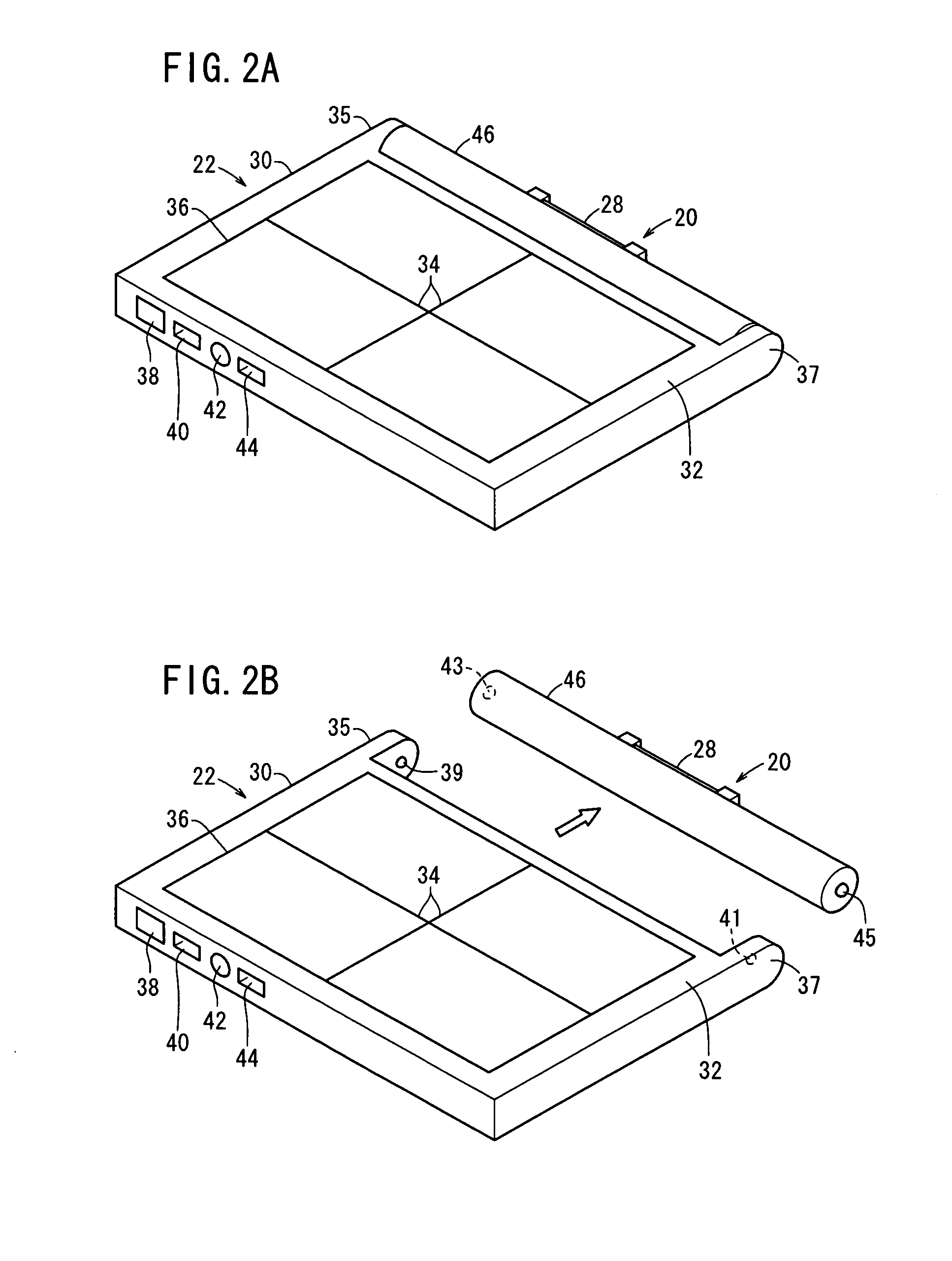
In a radiographic image capturing system and radiographic image capturing method, in a case that at least two radiation sources are housed in a radiation output device, weighting of doses of respective radiation emitted from the at least two radiation sources is carried out. Thereafter, respective radiation is applied to a subject from the at least two radiation sources in accordance with the weighting. Then, the radiation detecting device detects the respective radiation that has passed through the subject and converts the detected radiation into a radiographic image.

Description

CROSS-REFERENCE TO RELATED APPLICATION[0001]This application is based upon and claims the benefit of priority from Japanese Patent Applications No. 2010-187298 filed on Aug. 24, 2010, No. 2010-187300 filed on Aug. 24, 2010, No. 2010-187303 filed on Aug. 24, 2010, No. 2011-179091 filed on Aug. 18, 2011, No. 2011-179092 filed on Aug. 18, 2011 and No. 2011-179096 filed on Aug. 18, 2011, of which the contents are incorporated herein by reference.BACKGROUND OF THE INVENTION[0002]1. Field of the Invention[0003]The present invention relates to a radiographic image capturing system and a radiographic image capturing method for applying radiation from a plurality of radiation sources housed in a radiation output device to a subject, detecting radiation that has passed through the subject with a radiation detecting device, and converting the detected radiation into radiographic images.[0004]2. Description of the Related Art[0005]In the medical field, there have widely been used radiographic i...

Claims


Application Information

Patent Timeline
IPC IPC(8): G01N23/04
CPCA61B6/00A61B6/4007A61B6/4452A61B6/4423A61B6/5205A61B6/542A61B6/56A61B6/505
Inventor OHTA, YASUNORINISHINO, NAOYUKI
Owner FUJIFILM CORP
Learn More