Wind turbine with auxiliary fins

Active Publication Date: 2012-03-01
GENERAL ELECTRIC CO
View PDF8 Cites 19 Cited by
  • Summary
  • Abstract
  • Description
  • Claims
  • Application Information

AI Technical Summary

Benefits of technology

[0009]The present invention also encompasses various method embodiments for improving the efficiency of any manner of erected wind turbine by attaching aerodynamic fins in a fixed relationship relative to the rotor hub. The f

Problems solved by technology

The cost of producing the energ

Method used


Image

  • Wind turbine with auxiliary fins
  • Wind turbine with auxiliary fins
  • Wind turbine with auxiliary fins

Examples


Example

[0019]Reference now will be made in detail to embodiments of the invention, one or more examples of which are illustrated in the drawings. Each example is provided by way of explanation of the invention, and not as a limitation of the invention. In fact, it will be apparent to those skilled in the art that various modifications and variations can be made in the present invention without departing from the scope or spirit of the invention. For instance, features illustrated or described as part of one embodiment, can be used with another embodiment to yield a still further embodiment. Thus, it is intended that the present invention covers such modifications and variations as come within the scope of the appended claims and their equivalents.

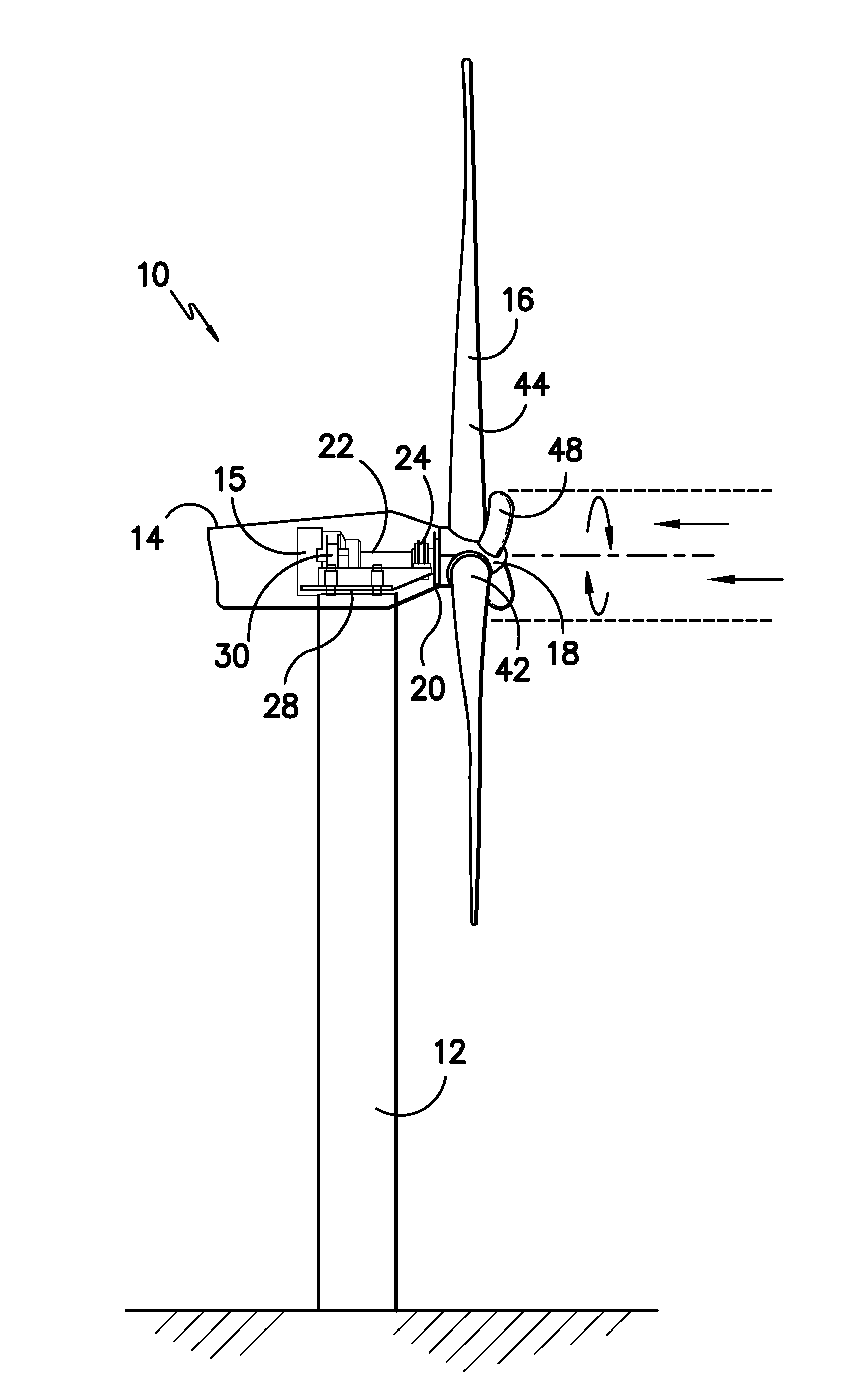
[0020]FIG. 1 illustrates a wind turbine 10 having various conventional components, including a tower 12 with a nacelle 14 mounted thereon. A plurality of turbine blades 16 are mounted to a rotor hub 18, which is in turn rotationally coupled to pow...


PUM


Abstract

A wind turbine includes a nacelle mounted atop a tower. Power generating components are housed within the nacelle. A rotor hub is rotationally coupled to the power generating components. A plurality of blades are fixed to the rotor hub. The blades include a root section extending radially outward from the rotor hub and an aerodynamic section extending radially outward from the root section, wherein lift is generated by the blades primarily along the aerodynamic section. Aerodynamic fins extend radially outward from the rotor hub alongside the root sections of the blades and have an aerodynamic shape so as to capture wind and impart rotational torque to the hub from a central impinging wind zone that is coaxial to the rotor hub and the blade root sections.

Description

FIELD OF THE INVENTION[0001]The present invention relates generally to wind turbines, and more particularly to a blade configuration for wind turbines.BACKGROUND OF THE INVENTION[0002]Turbine blades are the primary elements of wind turbines for converting wind energy into electrical energy. The blades have a cross-sectional profile of an airfoil such that, during operation, air flows over the blade producing a pressure difference between the sides. Consequently, a lift force, which is directed from a pressure side towards a suction side, acts on the blade. The lift force generates torque on the main rotor shaft, which is geared to a generator for producing electricity.[0003]Modern wind turbines can be quite large, with many designs having a rotor hub height exceeding 100 meters, and rotor diameters in excess of 80 meters. The blades have a root section mounted to rotor hub, with the aerodynamic shape of the blades defined radially outboard of the root section. This configuration res...

Claims


Application Information

Patent Timeline
IPC IPC(8): F01D15/10
CPCF03D1/025F03D1/0641F03D1/065F03D1/0658Y02E10/725F05B2240/30F05B2250/70Y02E10/721F05B2220/7066F03D15/10F03D9/25Y02E10/72
Inventor BAGEPALLI, BHARATGADRE, ANIRUDDHA D.BHATE, NITIN NARAYAN
Owner GENERAL ELECTRIC CO
Why Eureka
Try Eureka