
Suspension control apparatus

Active Publication Date: 2012-03-01
HITACHI AUTOMOTIVE SYST LTD
View PDF16 Cites 39 Cited by
  • Summary
  • Abstract
  • Description
  • Claims
  • Application Information

AI Technical Summary

Benefits of technology

[0007]The present invention has been made in view of the problems described above, and therefore has an object to provide a suspension control apparatus for controlling a wheel load of a wheel according to a lateral acceleration of a vehicle so as to enhance stability of the vehicle.

Problems solved by technology

By the way, the suspension control apparatus described in Japanese Patent Application Laid-open No. 2003-11635 does not control the damping-force adjusting type shock absorber when the antiskid brake system is not actuated.
Therefore, the potential of occurrence of an unstable running state of the vehicle remains the same.
Therefore, the suspension control apparatus described in Japanese Patent Application Laid-open No. 2003-11635 does not have the effects of reducing a likelihood of bringing about the unstable running state described above.
Therefore, there is a problem in that the wheel loads cannot be controlled in such a state and hence, running stability cannot be improved.
However, the configuration described in Non-Patent Document 1 takes only deceleration control of the vehicle into main consideration and does not take the application to the suspension control apparatus into consideration.

Method used


Image

  • Suspension control apparatus
  • Suspension control apparatus
  • Suspension control apparatus

Examples


first embodiment

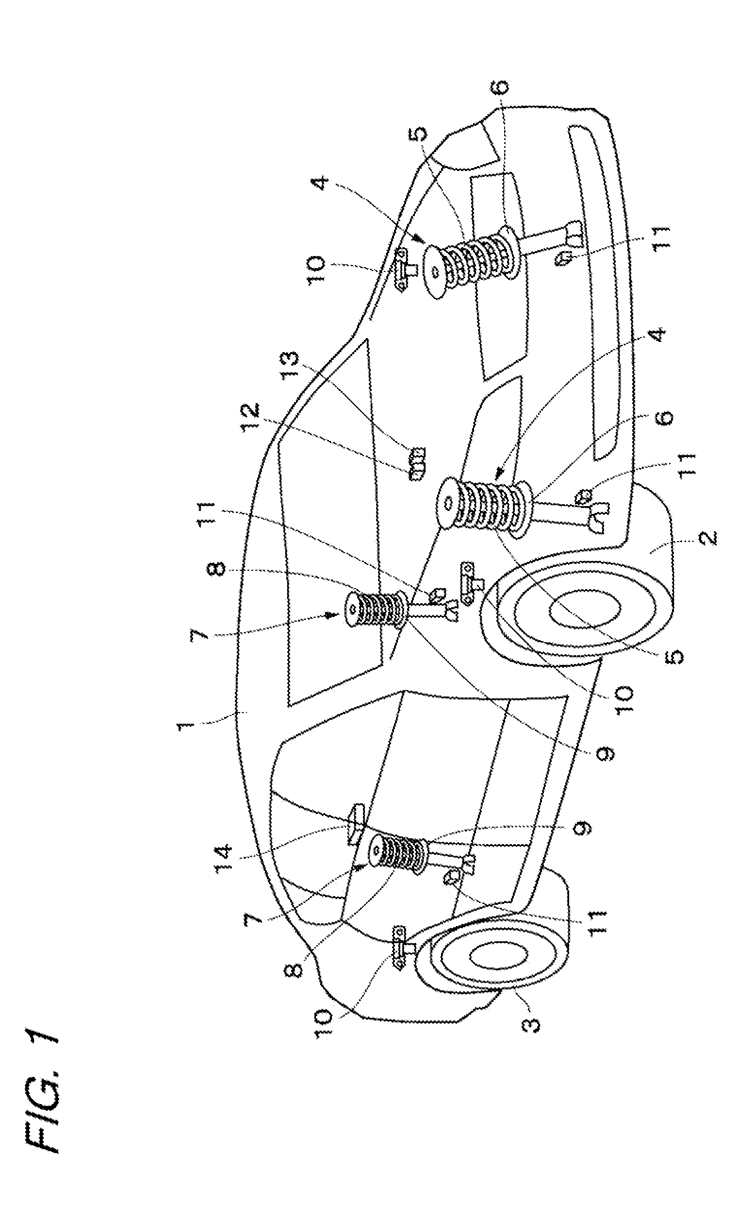
[0021]FIGS. 1 to 7 illustrate the present invention. FIG. 1 illustrates a vehicle body 1 constituting a body of a vehicle. Below the vehicle body 1, for example, right and left front wheels 2 (only one thereof is shown) and right and left rear wheels 3 (only one thereof is shown) are provided.

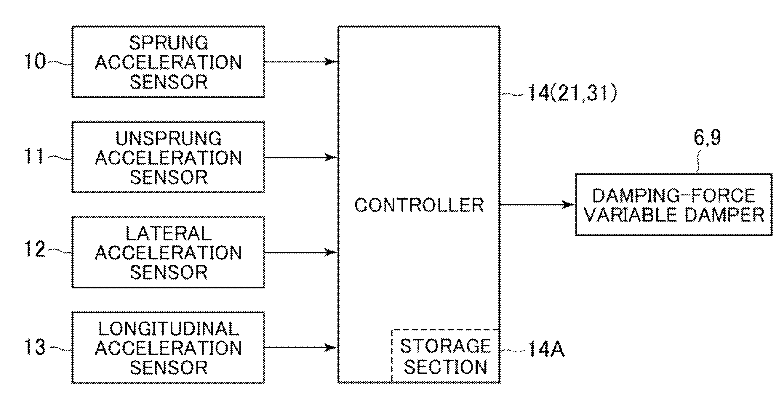
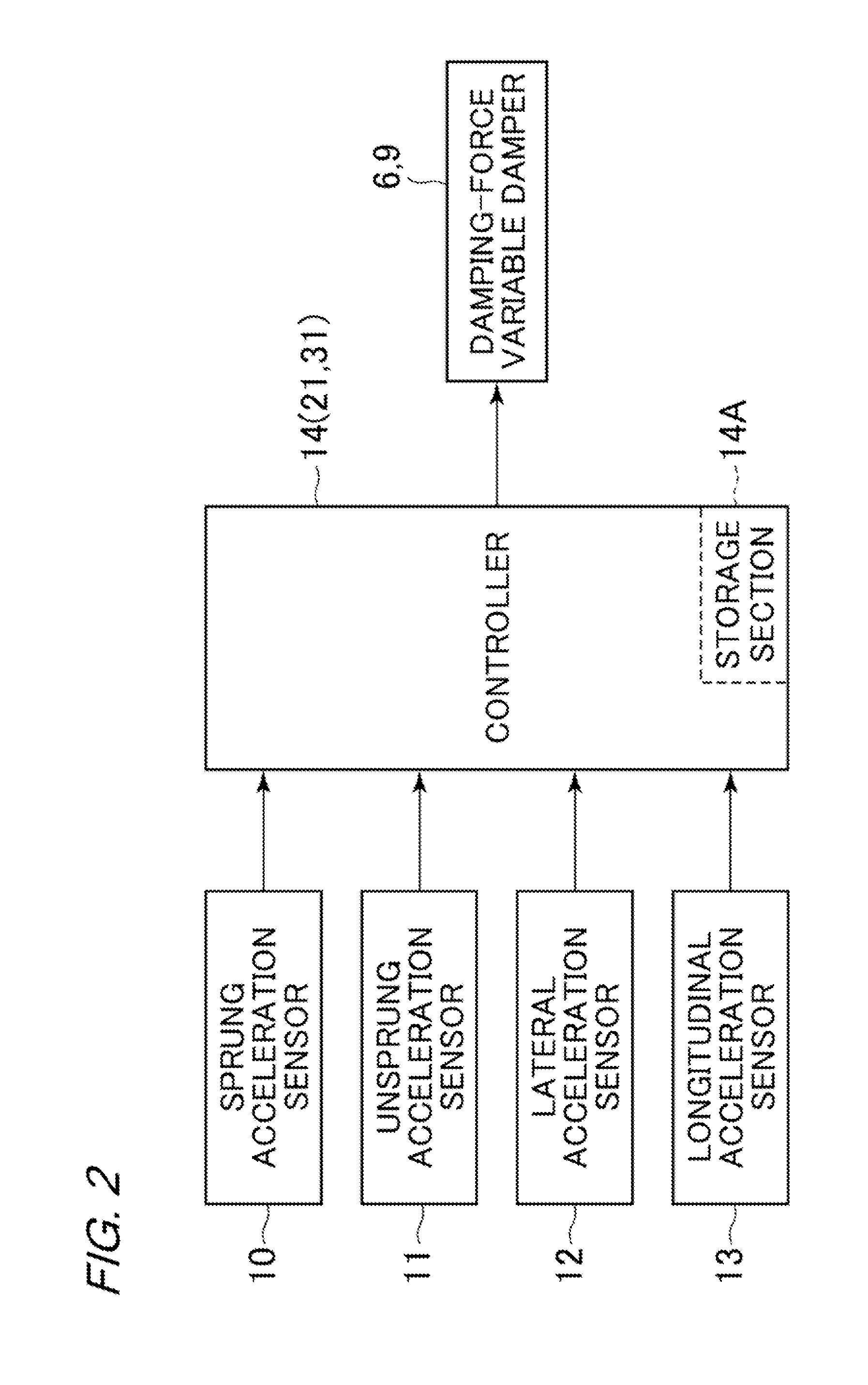
[0022]Front-wheel side suspension devices 4 are provided between the right front wheel 2 side and the vehicle body 1 and between the left front wheel 2 side and the vehicle body 1, respectively. One of the front-wheel side suspension devices 4 includes a right suspension spring 5 (hereinafter, referred to simply as “spring 5”) and a right damping-force adjusting type shock absorber 6 (hereinafter, referred to as “damping-force variable damper 6” provided between the right front wheel 2 side and the vehicle body 1 in parallel to the right spring 5. In the same manner, the other front-wheel side suspension device 4 includes a left spring 5 and a left damping-force variable damper 6 provided betwe...

second embodiment

[0074]The control identification processing is described referring to FIG. 8. First, in Step 31, the lateral acceleration Ay is subjected to temporal differentiation to compute the lateral jerk (dAy / dt). Next, in Step 32, the control identification coefficient is computed based on the lateral acceleration Ay and the longitudinal acceleration Ax, as expressed by Formula 5 below. More specifically, in the tern of Formula 5, which is proportional to the longitudinal acceleration Ax, a squared part of the sign function becomes 1 when the lateral acceleration Ay is other than zero (Ay≠0). Therefore, zero is obtained by the calculation. On the other hand, in the term proportional to the longitudinal acceleration Ax, the longitudinal acceleration Ax is directly calculated when the lateral acceleration Ay is zero. As a result, in the term of Formula 5, which is proportional to the longitudinal acceleration Ax, a component obtained when the lateral acceleration Ay does not change is compute...

third embodiment

[0083]The control gains KFR and KRR are now specifically described for the computation processing. As expressed by Formulae 6 and 7, when a product of the longitudinal acceleration Ax, the lateral acceleration Ay, and the lateral jerk (dAy / dt) is positive, the values of the control gains KFR and KRR are increased according to a magnitude of the longitudinal acceleration Ax. On the other hand, when the product of the longitudinal acceleration Ax, the lateral acceleration Ay, and the lateral jerk (dAy / dt) is negative, the values of the control gains KFR and KRR are reduced according to the magnitude of the longitudinal acceleration Ax. The reason for the computations described above is as follows.

[0084]In the G-Vectoring control, if the driver accelerates (Ax>0) when the deceleration is to be performed because the product of the lateral acceleration Ay and the lateral jerk (dAy / dt) is positive or the driver decelerates (Axy and the lateral jerk (dAy / dt) is negative, it becomes diffic...


PUM


Abstract

To control a wheel load of a wheel according to a lateral acceleration of a vehicle so as to enhance stability of the vehicle, provided is a suspension control apparatus, which is configured to control a wheel-load adjusting mechanism in at least one of the following manners: the wheel load of a front wheel is increased or is made unlikely to be reduced relative to the wheel load of a rear wheel when an absolute value of the lateral acceleration of the vehicle is increasing; and the wheel load of the rear wheel is increased or is made unlikely to be reduced relative to the wheel load of the front wheel when the absolute value of the lateral acceleration of the vehicle is reducing.

Description

BACKGROUND OF THE INVENTION[0001]The present invention relates to a suspension control apparatus to be mounted in a vehicle such as, for example, a four-wheeled automobile, which is suitably used for damping vibrations of the vehicle.[0002]In general, a suspension control apparatus is mounted in a vehicle such as an automobile as described in, for example, Japanese Patent Application Laid-open No. 2003-11635. The suspension control apparatus described in Japanese Patent Application Laid-open No. 2003-11635 includes a damping-force adjusting type shock absorber provided between a vehicle-body side and each axle side. The suspension control apparatus is configured to variably control damping-force characteristics obtained by the shock absorber according to a vehicle attitude caused with a braking operation of a brake.[0003]The suspension control apparatus described in Japanese Patent Application Laid-open No. 2003-11635 controls the damping-force adjusting type shock absorber so as to...

Claims


Application Information

Patent Timeline
IPC IPC(8): B60G17/016
CPCB60G17/08B60G2400/10B60G2400/102B60T2260/06B60G2400/106B60G2500/10B60T8/4031B60G2400/104
Inventor HARADA, NAOFUMI
Owner HITACHI AUTOMOTIVE SYST LTD
Learn More