Sampling frequency converter

a frequency converter and sampling frequency technology, applied in computing, electrophonic musical instruments, instruments, etc., can solve the problems of large data frequency fluctuation, unstable write request signal frequency, and large frequency fluctuation of subsequent stage devices, so as to reduce data frequency fluctuation. the effect of large latency of sampling frequency conversion

Inactive Publication Date: 2012-03-01
YAMAHA CORP
View PDF1 Cites 5 Cited by
  • Summary
  • Abstract
  • Description
  • Claims
  • Application Information

AI Technical Summary

Benefits of technology

[0013]In consideration of the situation described above, the object of the present invention is to provide a sampling frequency converter that is capable of keeping frequency fluctuation of data after sampling frequency conversion low, and reducing latency of sampling frequency conversion.
[0015]With this form of the invention, control is performed such that the frequency control information is corrected according to an increase or decrease in the pointer value of the speed correction pointer, and the writing speed follows the reading speed. Therefore, adjustment of the writing speed over a wide range, and fine adjustment of the writing speed near the reading speed can be performed according to an increase or decrease in the pointer value of the speed correction pointer without increasing the number of stages of the buffer. Consequently, it is possible to reduce frequency fluctuation of data after sampling frequency conversion without latency of the sampling frequency conversion becoming large.
[0017]With this form of the invention, control is performed such that the frequency control information is corrected according to an increase or decrease in the pointer value of the speed correction pointer, and the reading speed follows the writing speed. Therefore, adjustment of the reading speed over a wide range, and fine adjustment of the reading speed near the writing speed can be performed according to an increase or decrease in the pointer value of the speed correction pointer without increasing the number of stages of the buffer. Consequently, it is possible to reduce frequency fluctuation of data after sampling frequency conversion without latency of the sampling frequency conversion becoming large.

Problems solved by technology

This is because when this slope is large, the change in the frequency control information with respect to the difference from the reference value of the number of effective data becomes large, the frequency of the write request signal becomes unstable and frequency fluctuation occurs in the data after sampling frequency conversion.
Therefore, when the number of stages of the FIFO 102 or 104 is increased in order to reduce frequency fluctuation, there was a problem in that the latency from a time when a preceding stage device outputs data before sampling frequency conversion to a time when the data after sampling frequency conversion is supplied to a subsequent stage device becomes large.

Method used


Image

  • Sampling frequency converter
  • Sampling frequency converter
  • Sampling frequency converter

Examples


embodiment 1

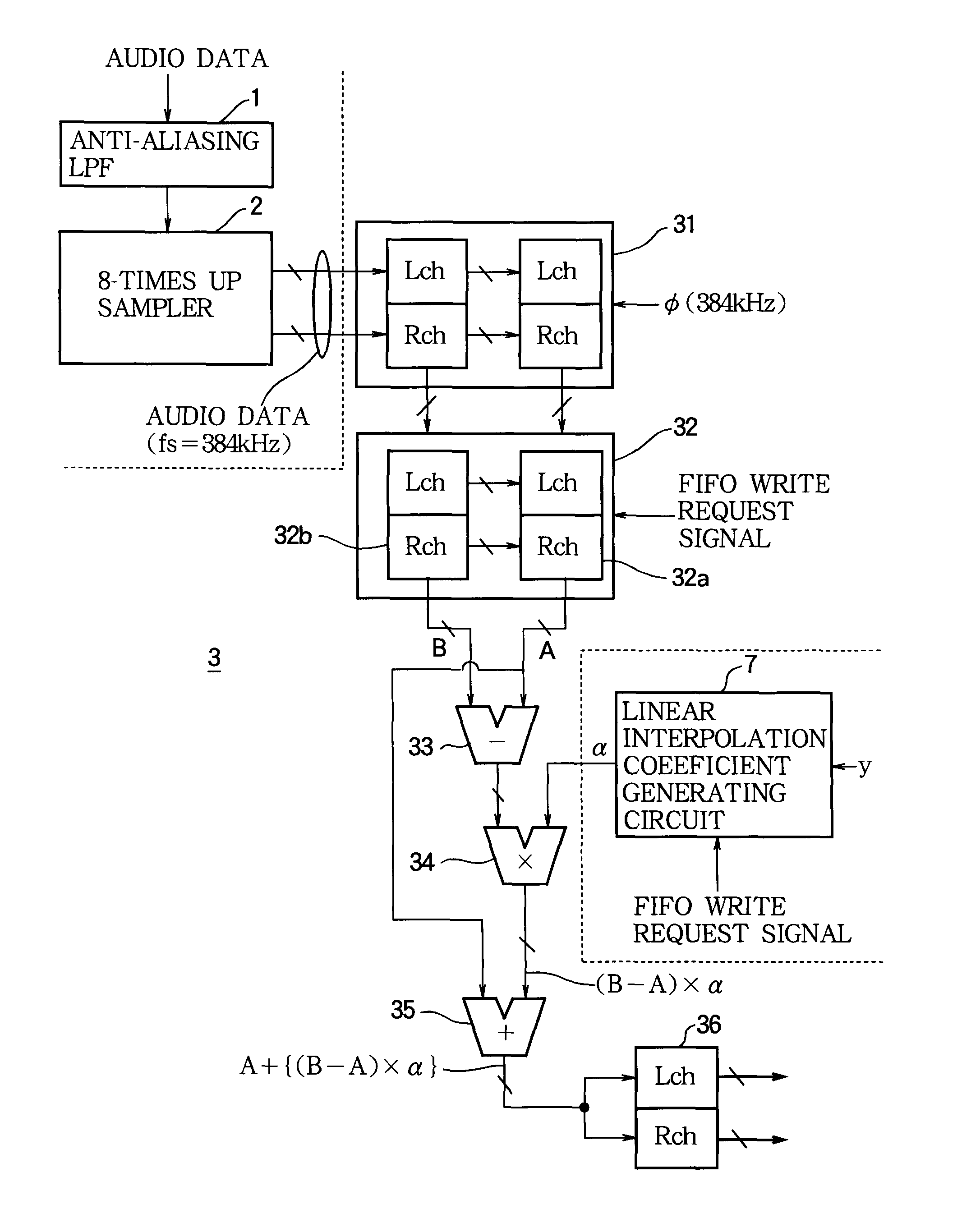
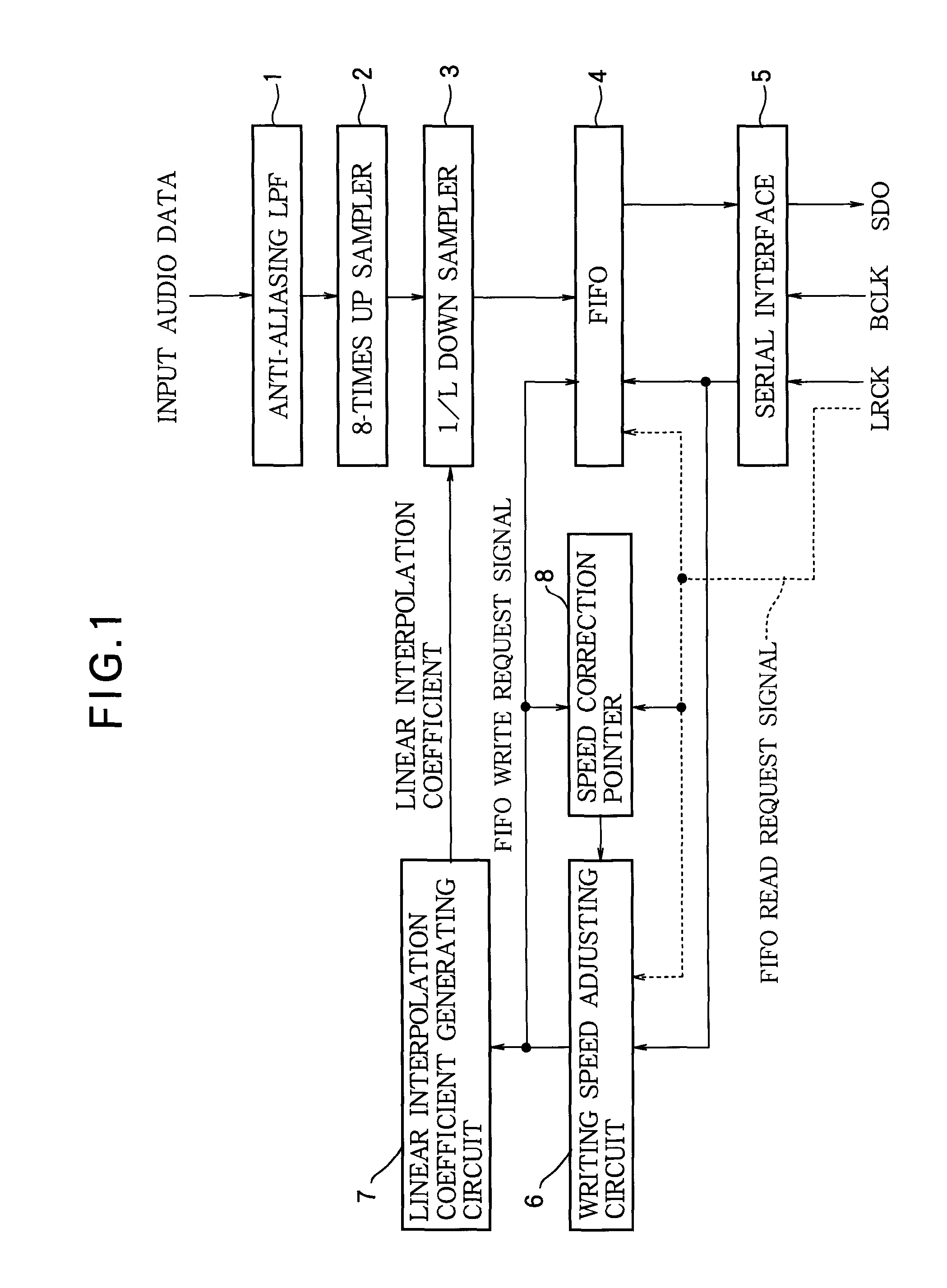
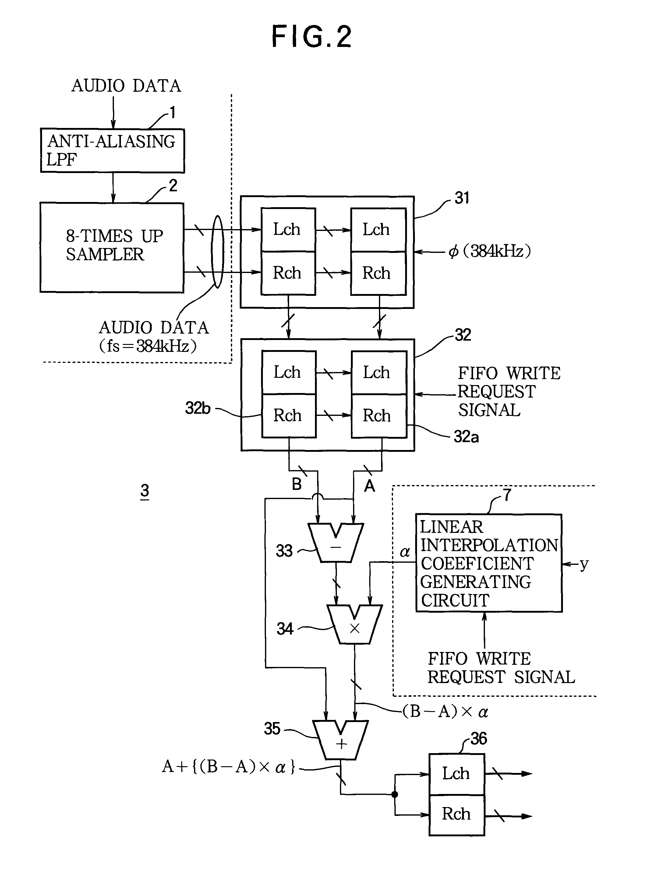
[0028]FIG. 1 is a block diagram illustrating the construction of a sampling frequency converter of a first embodiment of the present invention. In FIG. 1, an anti-aliasing LPF 1 is a circuit that performs LPF processing on input audio data in order to prevent folding noise from occurring in the sampling frequency conversion process. The sampling frequency converter of this embodiment receives input audio data having a first sampling frequency of 48 kHz, converts this data to audio data having a second sampling frequency that is selected from among nine types of sampling frequencies between 8 kHz and 48 kHz, and outputs the result. The anti-aliasing LPF 1 uses half of this selected second sampling frequency as a cutoff frequency, and removes the frequency component that is equal to or greater than this cutoff frequency from the input audio data.

[0029]An 8-times up-sampler 2 is a circuit that performs 8-times up sampling of the audio data having the first sampling frequency that is ou...

embodiment 2

[0055]FIG. 6 is a block diagram illustrating the construction of a sampling frequency converter of a second embodiment of the present invention. In this embodiment, the construction and role of the anti-aliasing LPF 1 and 8-times up sampler 2 are the same as in the first embodiment (FIG. 1) above. In this embodiment, the positional relationship between the FIFO 4 and 1 / L down sampler 3 is switched from the first embodiment.

[0056]In more detail, in response to a write request signal, the FIFO 4 stores audio data having a first sampling frequency that is outputted from the 8-times up sampler 2 and outputs the stored audio data in order starting from the oldest one. The speed correction pointer 8 is a pointer that is incremented when a FIFO write request signal is generated, and is decremented when a FIFO read request signal is generated.

[0057]A reading speed adjusting circuit 9 is a circuit that generates a FIFO read request signal that has the same time rate as the average time rate ...


PUM


Abstract

A sampling frequency converter has a buffer that stores data in response to a write request signal, and outputs stored data in order from the oldest data in response to a read request signal. An interpolation unit sequentially receives data from an external source, performs an interpolation operation at a generation timing of a write request signal for calculating interpolated data from a specified number of the most recently received data, and supplies the interpolated data to the buffer. A writing speed adjusting unit recurrently generates a write request signal at a time rate determined according to frequency control information. A speed correction pointer increases a pointer value each time a write request signal is generated, and decreases the pointer value each time a read request signal is generated. A frequency control unit corrects the frequency control information based on the pointer value of the speed correction pointer.

Description

BACKGROUND OF THE INVENTION[0001]1. Technical Field[0002]The present invention relates to a sampling frequency converter that is suitable for use in a digital audio device.[0003]2. Related Art[0004]As this kind of sampling frequency converter, there is a known converter that provides data after sampling frequency conversion to a subsequent stage device via a FIFO (First-In First-Out buffer), or there is a known converter that obtains data before sampling frequency conversion from a preceding stage device. FIG. 7 is a block diagram illustrating an example of the construction of the former sampling frequency converter, and FIG. 8 is a block diagram illustrating an example of the construction of the latter sampling frequency converter.[0005]In the sampling frequency converter illustrated in FIG. 7, an interpolator 101 is a circuit that stores data that is sequentially received from a preceding stage device, and when a write request signal is generated, performs interpolation from a spe...

Claims


Application Information

Patent Timeline
Patent Type & Authority Applications(United States)
IPC IPC(8): G06F12/00
CPCH03H17/0642G10H2250/631G10H2250/545
Inventor MURAKI, YASUYUKI
Owner YAMAHA CORP
Why Eureka
Try Eureka