Method of repairing bearing of wind turbine generator

a technology of wind turbine generator and bearing, which is applied in the direction of electric generator control, forging/pressing/hammering apparatus, final product manufacturing, etc., can solve the problems of reducing the thickness of the member on the apparatus side, affecting the work efficiency of the machine, and affecting the operation of the machine. , to achieve the effect of greatly increasing the work efficiency

Active Publication Date: 2012-03-08
MITSUBISHI HEAVY IND LTD
View PDF2 Cites 19 Cited by
  • Summary
  • Abstract
  • Description
  • Claims
  • Application Information

AI Technical Summary

Benefits of technology

[0030]In this manner, in a case where the main bearing is separated from the nacelle bedplate, even in a state where the main bearing is attached to the main shaft inner cylinder and the main shaft outer cylinder of the wind turbine generator, it is possible to insert the plate into the gap between the outer ring of the main bearing and the main shaft outer cylinder over the entire circumference of the main bearing. Accordingly, the repair is able to be performed by the bearing repairing method described above, without detaching the main bearing from the wind turbine generator, so that work efficiency is greatly increased.
[0031]In the present invention, since the plate is inserted between the constituent member (the member on the apparat

Problems solved by technology

However, even if the bearings described in Patent Documents 1 and 2 are used in the wind turbine generator, there is a case where the following problems occur.
However, the bearing ring of the bearing is rotated with respect to the member on the apparatus side due to a sudden high-load, so that the member on the apparatus side is often reduced in thickness due to

Method used


Image

  • Method of repairing bearing of wind turbine generator
  • Method of repairing bearing of wind turbine generator
  • Method of repairing bearing of wind turbine generator

Examples


Embodiment Construction

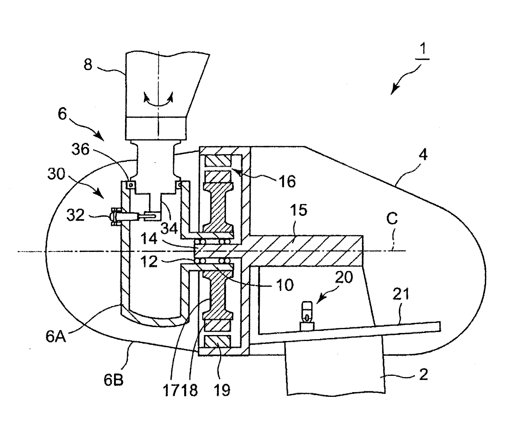
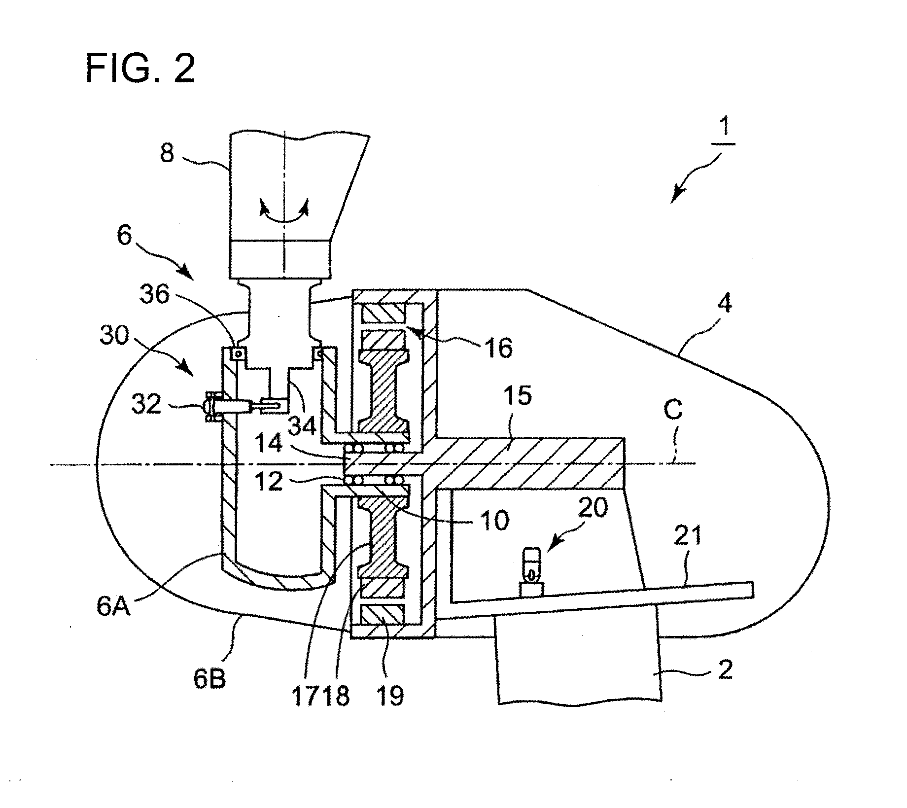
[0039]Hereinafter, an embodiment of the present invention will be described with reference to the accompanying drawings. Unless specific description is particularly provided, however, dimensions, materials, shapes, relative arrangement, and so on of constituent parts which are described in the embodiment are not intended to limit the scope of the invention only thereto, but shall be interpreted as illustrative only.

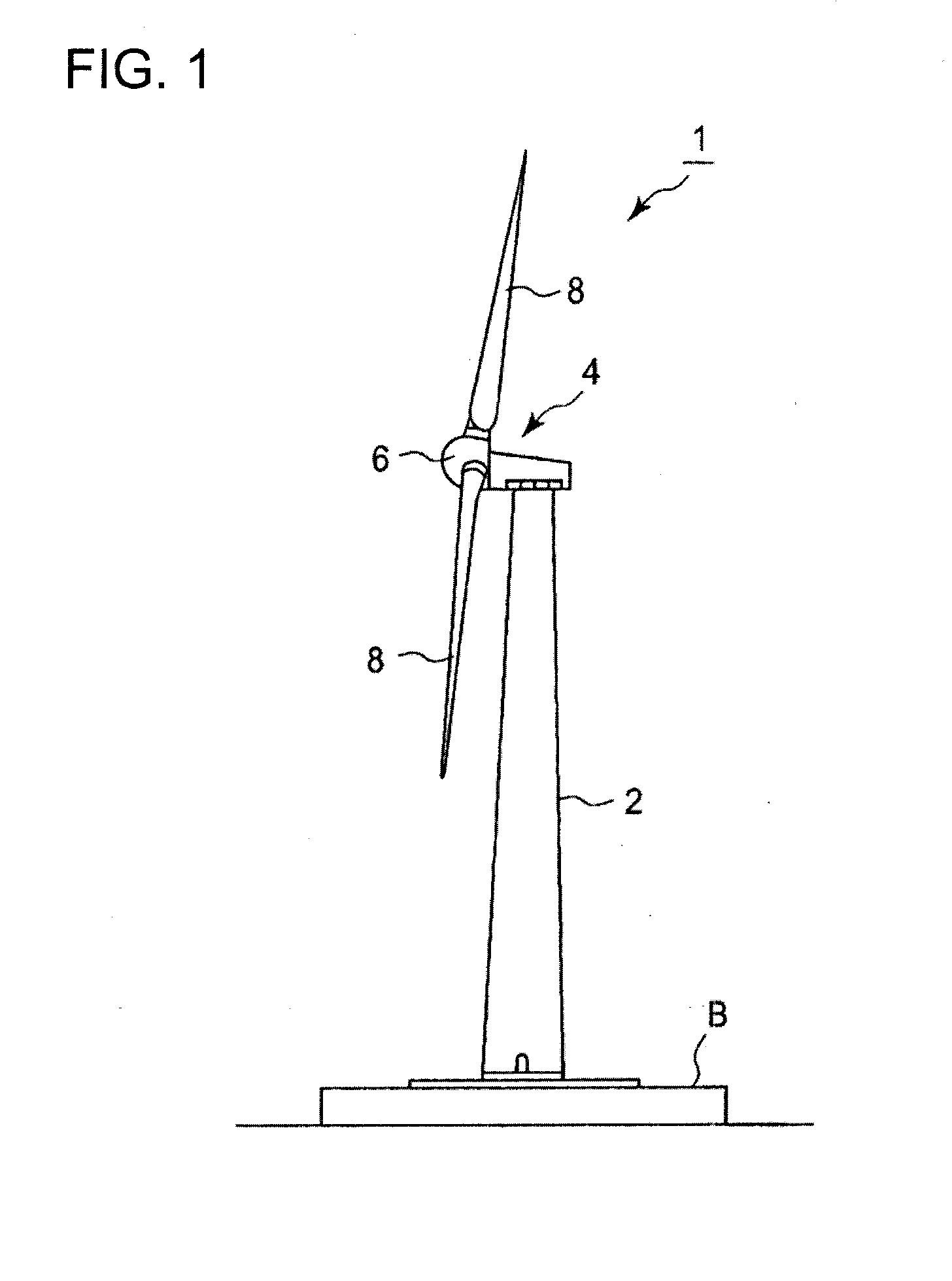
[0040]In the following, first, one example of a wind turbine generator to which a bearing repairing method according to the present invention is applied will be described, and then the bearing repairing method according to the present invention will be described in detail. Also, here, although a wind turbine generator of a so-called synchronous generator form is described as one example of the wind turbine generator, it goes without saying that the bearing repairing method according to the present invention is able to be applied to not only the wind turbine generator of a...


PUM

PropertyMeasurementUnit
Volumeaaaaaaaaaa
Currentaaaaaaaaaa
Frictionaaaaaaaaaa

Abstract

A method of repairing a bearing of a wind turbine generator is provided which is able to more permanently repair a gap which occurred between a constituent member of the wind turbine generator and a bearing ring of the bearing. For example, in the case of repairing the gap 13 between the main shaft outer cylinder 10 of the wind turbine generator 1 and the outer ring 12A of the main bearing 12, the plate 40 is inserted between the main shaft outer cylinder 10 and the outer ring 12A, and also the plate 40 is fixed to an inner circumferential surface of the main shaft outer cylinder 10 by the adhesive agent 41. On the other hand, slip is permitted between the plate 40 and the outer ring 12A of the main bearing 12.

Description

BACKGROUND OF THE INVENTION[0001]1. Field of the Invention[0002]The present invention relates to a method of repairing a bearing of a wind turbine generator and in particular, to a bearing repairing method which fills up a gap between a constituent member such as a housing member or a shaft member of a wind turbine generator and a bearing ring of a bearing.[0003]2. Description of the Related Art[0004]In recent years, from the viewpoint of conservation of the global environment, the spread of wind turbine generators which use wind power as one form of renewable energy is progressing.[0005]A wind turbine generator is generally constituted by a rotor head to which blades are attached, a nacelle which houses a rotary shaft and a generator, and a tower which supports the nacelle. Also, in order to improve power generation efficiency, yaw rotation which swivels the nacelle in accordance with the state of the wind, or pitch control which rotates the blades in a pitch direction is often per...

Claims


Application Information

Patent Timeline
IPC IPC(8): B23P6/00
CPCF03D1/003F03D11/0008F05B2230/80F16C35/077Y02E10/726Y10T29/49332Y10T29/49316Y10T29/49638Y10T29/49327Y10T29/49318Y02E10/722F16C2237/00F16C2360/31F03D80/50F03D80/70Y02E10/72Y02P70/50F05B2240/50
Inventor KAWANO, KEIICHIROUIWASAKI, KAORUMATSUNAMI, YUJITAKADA, SHIROAKIZUKI, YUKIOTAKEUCHI, HIROAKI
Owner MITSUBISHI HEAVY IND LTD
Why Eureka
Try Eureka