Method and Apparatus for Controlling Gas Turbine Combustor

a technology of gas turbine combustor and combustor body, which is applied in the direction of mechanical equipment, machines/engines, lighting and heating equipment, etc., to achieve the effect of reducing nox emission

Inactive Publication Date: 2012-03-08
MITSUBISHI HITACHIPOWER SYST LTD
View PDF5 Cites 6 Cited by
  • Summary
  • Abstract
  • Description
  • Claims
  • Application Information

AI Technical Summary

Benefits of technology

[0024]According to the present invention, a method and an apparatus for controlling a gas turbine combustor capable of ensuring combustion stability

Problems solved by technology

When the full speed no-load operation state after the load dump is held for many hours, the independent diffusion combustion state of a high NOx

Method used


Image

  • Method and Apparatus for Controlling Gas Turbine Combustor
  • Method and Apparatus for Controlling Gas Turbine Combustor
  • Method and Apparatus for Controlling Gas Turbine Combustor

Examples


embodiment 1

[0045]The control apparatus of the gas turbine combustor and the control method of the gas turbine combustor of the first embodiment of the present invention will be explained by referring to FIGS. 1 to 3.

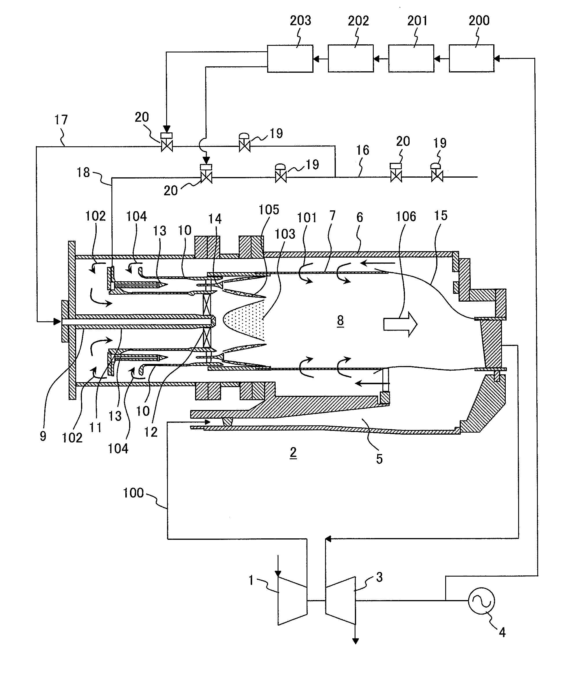
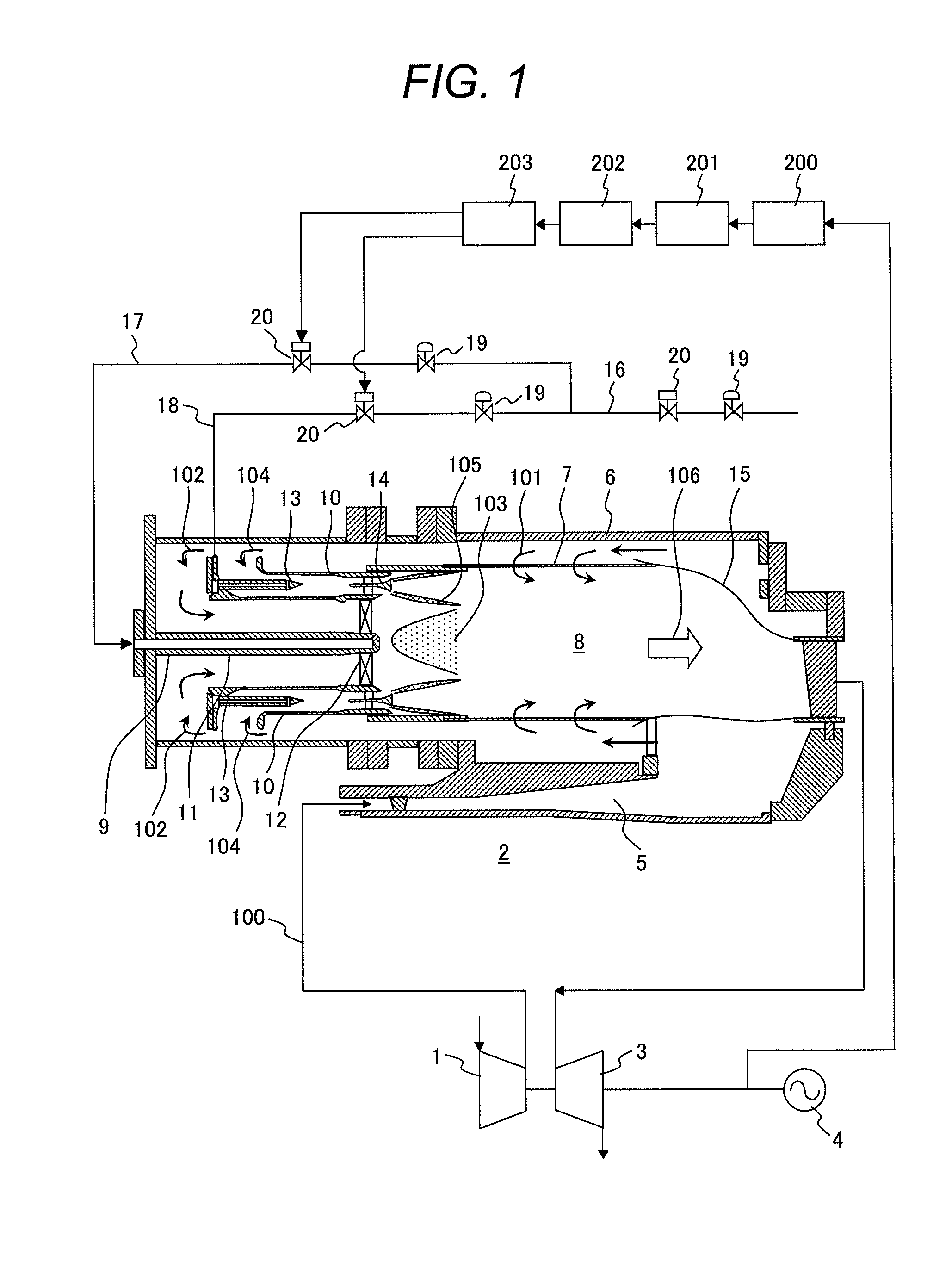
[0046]FIG. 1 shows an entire drawing of the gas turbine unit for power generation having the gas turbine combustor which is the first embodiment of the present invention, and the gas turbine unit includes a compressor 1, a gas turbine combustor 2, and a turbine 3, and by the output of the turbine 3, a generator 4 is rotated, thus power is obtained.

[0047]Compressed air 100 compressed by the compressor 1 flows into the gas turbine combustor 2 via a diffuser 5 and passes between an outer sleeve 6 and a combustor liner 7.

[0048]A part of the compressed air 100 flows into a combustion chamber 8 of the gas turbine combustor 2 as cooling air 101 of the combustor liner 7. The compressed air 100 not used as cooling air 101 respectively flows into a diffusion combustion burner 9 arranged on t...

embodiment 2

[0070]Next, the control apparatus of the gas turbine combustor and the control method of the gas turbine combustor of the second embodiment of the present invention will be explained by referring to FIGS. 4 and 5. The control apparatus of the gas turbine combustor 2 of the second embodiment of the present invention is the same as that of the gas turbine combustor 2 of the first embodiment shown in FIGS. 1 to 3 in the basic constitution, so that the explanation common to the two is omitted and only the different portions will be explained below.

[0071]FIG. 4 shows an entire drawing of the gas turbine unit for power generation including the gas turbine combustor 2 which is the second embodiment of the present invention and the control apparatus of the gas turbine combustor 2 of this embodiment, in addition to the constitution of the gas turbine combustor 2 of the first embodiment, is structured so as to install a rotating speed comparison arithmetic unit 204 for comparing a set switchi...

embodiment 3

[0081]Next, the control apparatus of the gas turbine combustor and the control method of the gas turbine combustor of the third embodiment of the present invention will be explained by referring to FIGS. 6 and 7. The control apparatus of the gas turbine combustor 2 of the third embodiment of the present invention is the same as that of the gas turbine combustor 2 of the first embodiment shown in FIGS. 1 to 3 in the basic constitution, so that the explanation common to the two is omitted and only the different portions will be explained below.

[0082]FIG. 6 shows an entire drawing of the gas turbine unit for power generation including the gas turbine combustor 2 which is the third embodiment of the present invention and the gas turbine combustor 2 of this embodiment, in addition to the constitution of the gas turbine combustor 2 of the first embodiment, is structured so as to install a switching rotating speed arithmetic unit 206 for calculating the rotating speed of the gas turbine to...


PUM


Abstract

An apparatus for controlling a gas turbine combustor having a diffusion combustion burner and a premix combustion burner comprising: a rotating speed detector for detecting a rotating speed of gas turbine, a recorder for recording the detected value of the rotating speed of gas turbine detected by the rotating speed detector, an arithmetic unit for calculating a change with time of the rotating speed of gas turbine in accordance with details of the detected value of the rotating speed of gas turbine recorded in the recorder, and a fuel control unit for judging a starting situation of reduction in the rotating speed of gas turbine on the basis of the change with time of the rotating speed of gas turbine calculated by the arithmetic unit and controlling respectively a fuel flow rate for the diffusion combustion burner to be fed to the diffusion combustion burner installed in the gas turbine combustor and a fuel flow rate for the premix combustion to be fed to the premix combustion burner.

Description

CLAIM OF PRIORITY[0001]The present application claims priority from Japanese patent application JP 2010-198518 filed on Sep. 6, 2010, the content of which is hereby incorporated by reference into this application.BACKGROUND OF THE INVENTION[0002]1. Field of the Invention[0003]The present invention relates to a method and an apparatus for controlling a gas turbine combustor.[0004]2. Description of Related Art[0005]In the gas turbine combustor, there are a diffusion combustor and a premix combustor available. The diffusion combustor is a system for separately feeding and burning fuel and air in a combustion chamber, and a flame is formed in a state close to the stoichiometric ratio of fuel to air, and the local flame temperature rises, so that although the combustion stability is high, the nitrogen oxide (NOx) emission increases.[0006]On the other hand, the premix combustor is a system for premixing fuel and air and then feeding and burning them in the combustion chamber, and the mixi...

Claims


Application Information

Patent Timeline
IPC IPC(8): F23R3/28
CPCF02C9/28F05D2270/091F02C9/46F05D2270/331F05D2270/31F02C9/34F23N1/002F05D2270/304F05D2270/309F05D2270/082F23N2241/20F02C9/263
Inventor SEKIGUCHI, TATSUYAYOSHIDA, SHOUHEIHIRATA, YOSHITAKAHAYASHI, AKINORISAITOU, NOZOMITAKAHASHI, KAZUOSAITOU, TAKEO
Owner MITSUBISHI HITACHIPOWER SYST LTD
Why Eureka
Try Eureka