Relief printing plate, plate-making method for the relief printing plate and plate-making apparatus for the relief printing plate
a printing plate and relief technology, applied in the field of relief printing plates, can solve the problems of not being suitable for printing requiring high image quality, affecting the quality of printing, and affecting the reproduction effect of excellent highlights, so as to prevent the relief from falling over, improve the resistance to pressure against the relief serving as a highlight halftone dot, and improve the effect of reducing the number of printing plates
- Summary
- Abstract
- Description
- Claims
- Application Information
AI Technical Summary
Benefits of technology
Problems solved by technology
Method used
Image
Examples
first embodiment
of Three-Dimensional Conversion Method
[0069]FIG. 4 is a flowchart illustrating a three-dimensional conversion process of generating three-dimensional data containing depth data for control the laser engraver 16 based on binary image data and multi-value image data.
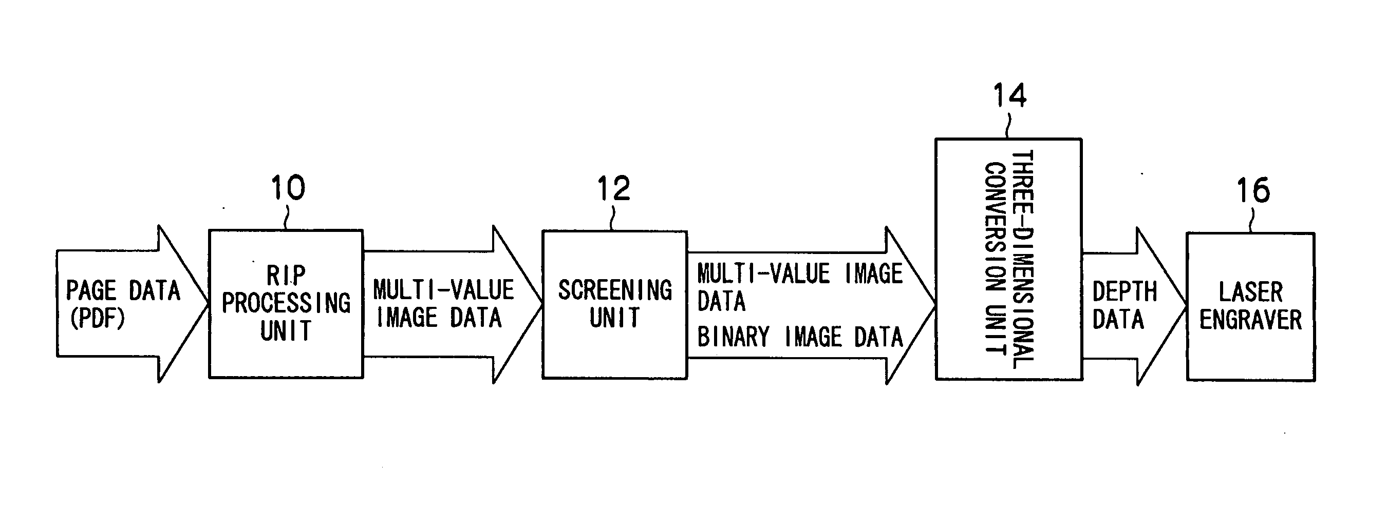
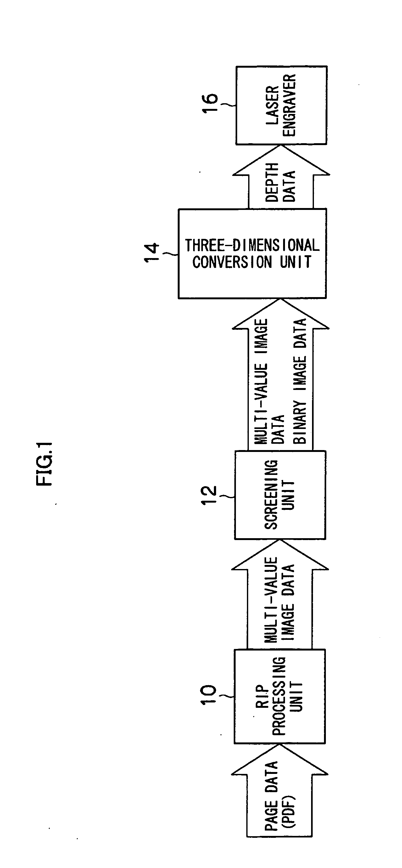
[0070]In FIG. 4, the three-dimensional conversion unit 14 (FIG. 1) inputs the screened binary image data and the multi-value image data representing a tone of each halftone dot (Steps S10 and S12).
[0071]Then, the three-dimensional conversion unit 14 uses the inputted binary image data and the multi-value image data to initialize the depth data (Step S14).
[0072]In this initialization, first, a depth data memory area, which has the same width / height as that of the screened binary image data, for the necessary number of bits (here 16 bits) capable of representing desired depth data is reserved. Then, the value of multi-value image data corresponding to each pixel of this depth data memory area is used as an input value to rea...
second embodiment
of Three-Dimensional Conversion Method
[0094]FIG. 11 is an enlarged view of the essential parts of a flexographic printer. As illustrated in FIG. 11, a substrate 3 is pinched and conveyed between a flexographic printing plate 1 mounted on a plate cylinder 4 and an impression cylinder 9 in a printing direction.
[0095]At this time, the flexographic printing plate 1 is slightly deformed by a pressure against the impression cylinder 9; a relief 1A and the substrate 3 move in contact with each other or spaced apart by a predetermined distance L (about 10 mm); and during this period, ink attached on an apex of the relief 1A is transferred to the substrate 3.
[0096]In the example of FIG. 11, the relief 1A is deformed by a pressure applied from the impression cylinder 9 via the substrate 3 so as to prevent slipping or sliding from occurring while the apex of the relief 1A is moving in contact with the substrate 3.
[0097]In contrast to this, if the relief 1A is not flexible in the printing direc...
PUM
 Abstract
Description
Claims
Application Information
 - R&D
- Intellectual Property
- Life Sciences
- Materials
- Tech Scout
- Unparalleled Data Quality
- Higher Quality Content
- 60% Fewer Hallucinations
Browse by: Latest US Patents, China's latest patents, Technical Efficacy Thesaurus, Application Domain, Technology Topic, Popular Technical Reports.
© 2025 PatSnap. All rights reserved.Legal|Privacy policy|Modern Slavery Act Transparency Statement|Sitemap|About US| Contact US: help@patsnap.com


