Exhaust flow control device for exhaust muffler

a technology of flow control and exhaust muffler, which is applied in the direction of machines/engines, mechanical equipment, gas passages, etc., can solve the problems of difficult to wide-open the valve plate, and difficulty in achieving the above-described characteristics during high-speed, high-load operation of engines, so as to reduce the sound of gas flow, increase the pressure in the muffler body, and reduce the back pressure

Active Publication Date: 2012-03-08
YUTAKA GIKEN CO LTD
View PDF10 Cites 13 Cited by
  • Summary
  • Abstract
  • Description
  • Claims
  • Application Information

AI Technical Summary

Benefits of technology

[0007]The present invention has been made in view of such circumstances. An object thereof is to provide an exhaust flow control device for an exhaust muffler, in which the valve-closing force of a valve spring for a valve plate decreases, or hardly changes, as the opening degree of the valve plate increases, thereby readily enabling wide opening of an exhaust flow control valve by an increase in the pressure in a muffler body during high speed, high-load operation of an engine, and achieving the characteristics of reduction in the back pressure and reduction in the gas flow sound.

Problems solved by technology

Thus, it becomes difficult to wide-open the valve plate, making it difficult to sufficiently obtain the above-described characteristics during high-speed, high-load operation of an engine.

Method used


Image

  • Exhaust flow control device for exhaust muffler
  • Exhaust flow control device for exhaust muffler
  • Exhaust flow control device for exhaust muffler

Examples


first embodiment

[0035]First, the present invention shown in FIGS. 1 to 5 will be described below.

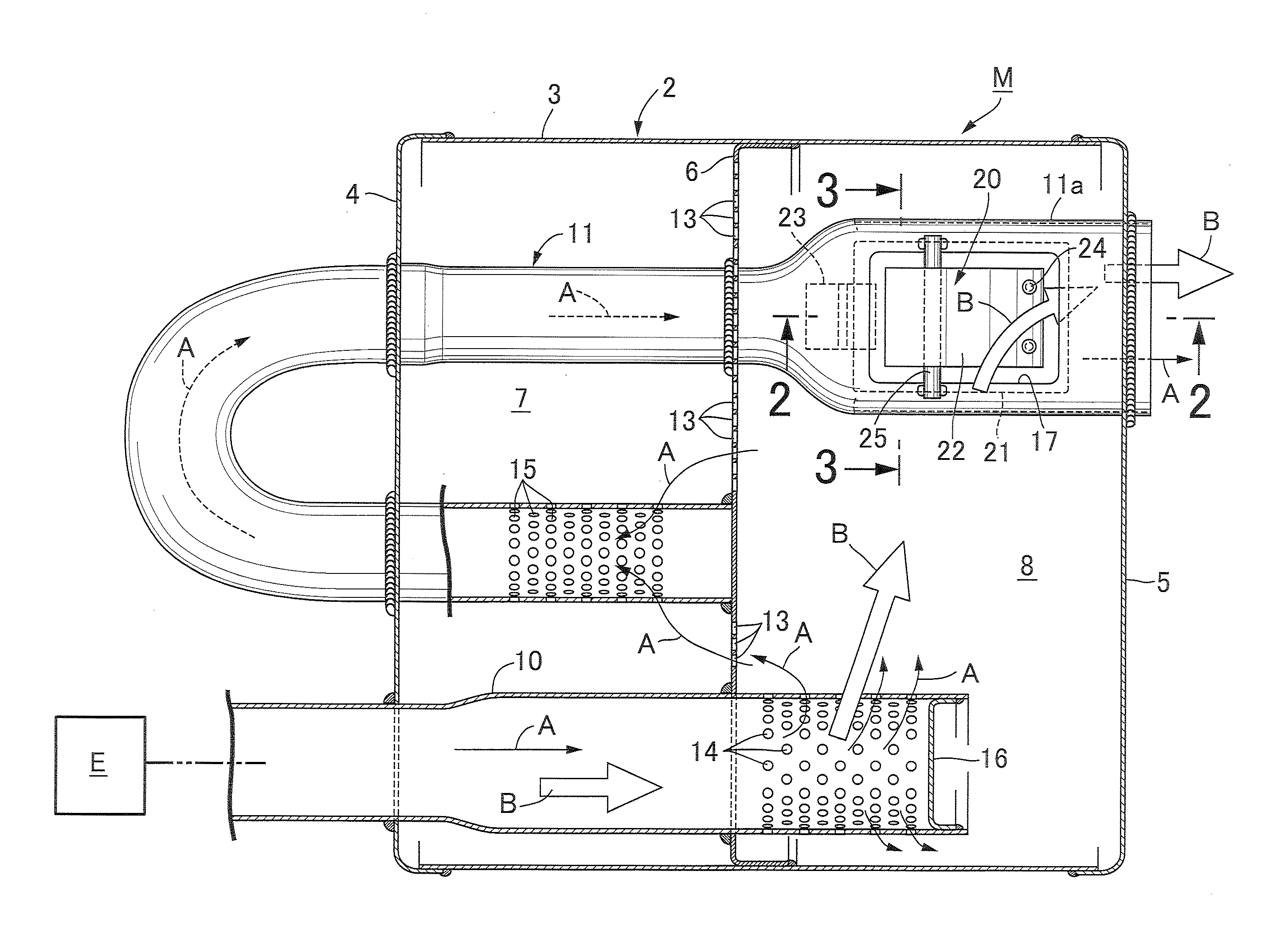
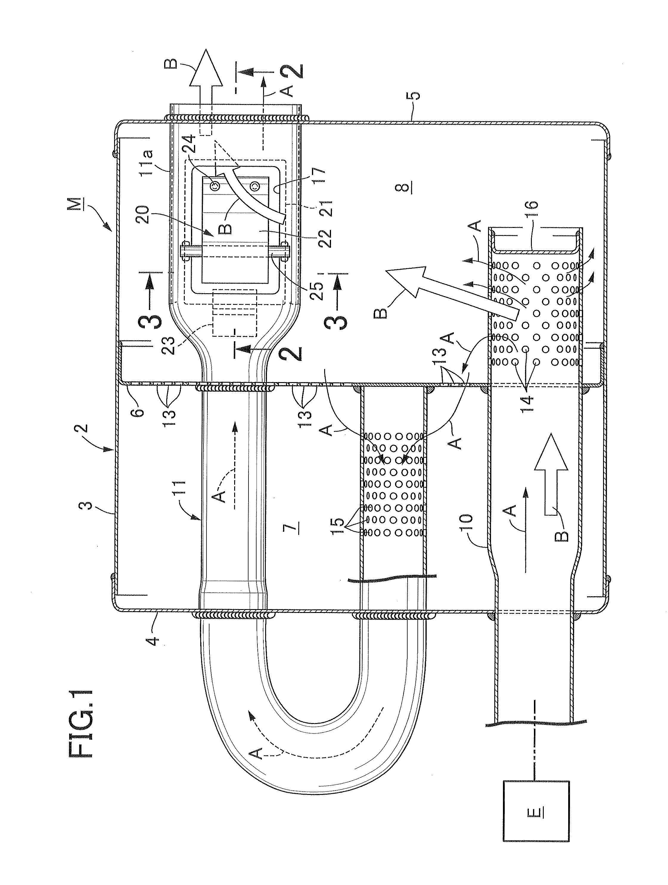
[0036]In FIG. 1, an exhaust muffler 1 for an automobile includes a muffler body 2, an upstream exhaust pipe 10, and a downstream exhaust pipe 11. The muffler body 2 is formed into a sealed drum shape by a trunk part 3, a front-side end plate 4, and a rear-side end plate 5 which are respectively welded to front and rear ends of the trunk part 3. The inside of the muffler body 2 is partitioned into a front-side silencing chamber 7 and a rear-side silencing chamber 8 by a partition wall plate 6 that is welded to an inner peripheral surface at an intermediate portion of the trunk part 3. The partition wall plate 6 has multiple first silencing holes 13 provided therein to allow communication between the two silencing chambers 7, 8.

[0037]The upstream exhaust pipe 10 has an upstream end connected to an exhaust port of an engine E, and penetrates the front-side end plate 4 and the partition wall plate 6, so tha...

second embodiment

[0052]Next, the present invention shown in FIGS. 6 to 9 will be described.

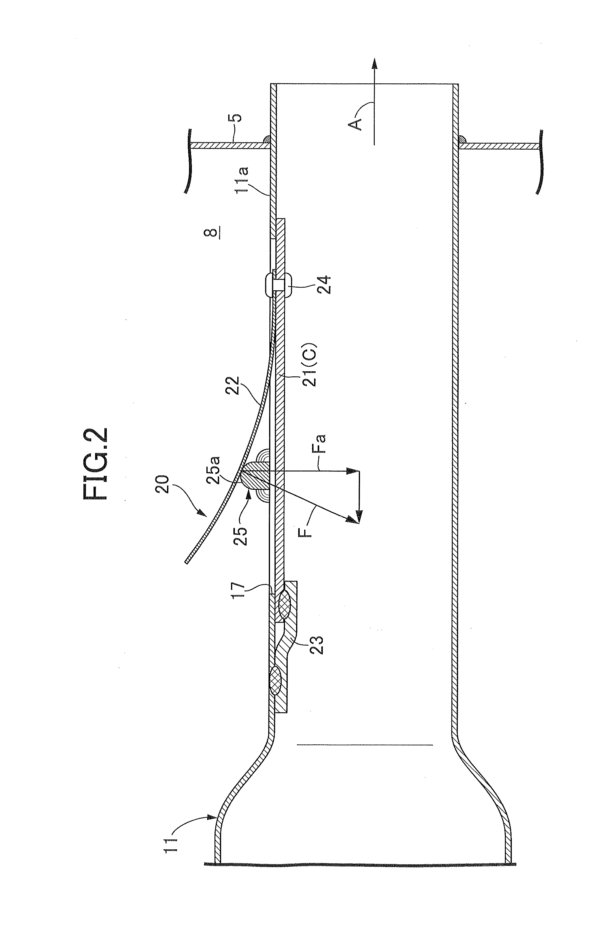
[0053]In the second embodiment, a hook-shaped hinge portion 21a is formed at the base end portion of the valve plate 21. The hinge portion 21a pivotably engages with a long hinge hole 27a of a support member 27 that is welded to the inner wall of the flattened pipe portion 11a. In addition, the spring receiving member 25 is formed as a partition wall 25 that results from punching of the short-cut hole 17 and remains on the flattened pipe portion 11a so as to partition the short-cut hole 17 into two. In a central portion of the partition wall 25, a raised portion 25b is formed which is raised higher than the outer surface of the downstream exhaust pipe 11. The valve spring 22 is in pressure contact with the raised portion 25b in a slidable manner.

[0054]The other constitutions are the same as those in the aforementioned embodiment. Portions corresponding to those in the above embodiment are denoted by the same r...

third embodiment

[0056]Next, the present invention shown in FIG. 10 will be described.

[0057]In the third embodiment, as a hinge connection structure of the valve plate 21 to the flattened pipe portion 11a, the same structure as that in the second embodiment is employed. In addition, the spring receiving member 25 that is in the first embodiment is employed. In FIG. 10, portions corresponding to those in the first and second embodiments are denoted by the same reference numerals, and overlapping descriptions are omitted.


PUM


Abstract

An exhaust flow control valve includes: a valve plate hinged to a downstream exhaust pipe to be pivotable, inside the pipe, between a fully closed position where a short-cut hole is closed and a fully open position where the short-cut hole is opened, the valve plate having a tip end directed toward a downstream side of the downstream exhaust pipe when at the fully open position; a spring receiving member provided to the downstream exhaust pipe to traverse the short-cut hole; and a valve spring having one end portion fastened to a tip end portion, which is located on the downstream side of the downstream exhaust pipe with respect to the spring receiving member, of the valve plate, and having an opposite end side being slidably in pressure contact with the spring receiving member, thereby generating a repulsive force to bias the valve plate toward the fully closed position.

Description

BACKGROUND OF THE INVENTION[0001]1. Field of the Invention[0002]The present invention relates to an improvement of an exhaust flow control, device for an exhaust muffler, comprising: a short-cut hole provided in an intermediate portion in a longitudinal direction of a downstream exhaust pipe connected to a muffler body, the downstream exhaust pipe having one end portion communicating with an inside of the muffler body and having an opposite end portion opened to atmospheric air, the short-cut hole allowing communication between the inside of the muffler body and an inside of the intermediate portion of the downstream exhaust pipe; and an exhaust flow control valve appended to the downstream exhaust pipe and configured to close the short-cut hole when a pressure in the muffler body is lower than a predetermined value, and open the short-cut hole when the pressure is at the predetermined value or higher.[0003]2. Description of the Related Art[0004]Such an exhaust flow control device f...

Claims


Application Information

Patent Timeline
Patent Type & Authority Applications(United States)
IPC IPC(8): F01N1/08
CPCF01N1/084F01N2470/02F01N1/166F01N1/163
Inventor MIIKE, KOJITSUDA, KAZUHIROOKOSHI, KATSUNORIGOTO, TAKATOSHI
Owner YUTAKA GIKEN CO LTD
Why Eureka
Try Eureka