Driving device for lifting buried spraying head

a driving device and hydraulic technology, applied in the direction of spraying apparatus, movable spraying apparatus, etc., can solve the problems of high demands on manufacturing accuracy and assembly accuracy of gears, high manufacturing and assembly difficulty of traditional injection pipe products, and reduce the rotary speed variation of spraying heads. , the effect of greatly simplifying manufacturing and assembly

Active Publication Date: 2012-03-08
GUANGDONG LIANSU TECH INDAL
View PDF3 Cites 9 Cited by
  • Summary
  • Abstract
  • Description
  • Claims
  • Application Information

AI Technical Summary

Benefits of technology

[0016]The invention provides a novel spraying head driving structure in which a spraying head rotates under the action of tangential viscous force generated by water viscosity, especially the tangential viscous force generated by water viscosity is utilized twice, water current flowing on the tangential flow generator in the tangential direction firstly drives the outer cylindrical surface of the hollow cylinder of the hydraulic rotator to rotate, through a main shaft the driving cylinder which acts as a driving cylinder drives the hydraulic driving disc to rotate, and acting as a driving disc the hydraulic driving disc rotates to causes water current near the disc to rotate due to water viscosity, and thus to drive a nozzle driving disc which is connected with a spraying head and concentric with the driving disc and acts as a driven disc to rotate. Such driving structure has two significant advantages: firstly, the driving structure has no gear pairs and airfoil impeller, only has a liquid friction cylinder pair, a liquid friction disc pair and at most two shafts (one shaft connects the driving cylinder and the driving disc, and the other shaft connects the driven disc and the spraying head, while traditional product has more gear shaft because of more gear pairs), and therefore, the manufacture and assembly are greatly simplified; and secondly, because there are one grade of soft connection driven by water tangential force from the driving cylinder to the spraying head, when water pressure changes, the variation of rotary speed of the driven shaft will retarded, so that the rotary speed variation of the spraying head is reduced.

Problems solved by technology

The traditional injection pipe product is complex in structure, having the structure that filtered water rushes at a multi-piece airfoil impeller positioned on an end surface at a certain angle to drive a main shaft to rotate, and a driving gear provided on the main shaft drives a nozzle to rotate after multi-grade gear pair deceleration, achieving the object of spraying.
In this driving structure, excess gear pairs brings high difficulty for manufacture and assembly; especially high rotating speed of the driving gear requires high mounting accuracy of each gear shaft and high manufacturing accuracy of each gear shaft hole; and particularly, because module of each gear is small, which is merely 0.5 basically, there are high demands on the manufacturing accuracy and the assembly accuracy of the gears.
Therefore, such driving structure has high manufacture cost.
Because gears are in hard connections from the first gear to the nozzle, when water pressure changes, the rotational angular velocity of the spraying head fluctuates directly along with the fluctuation of water pressure and varies obviously; and frequently variation of water pressure will damage gear pairs at all levels.

Method used


Image

  • Driving device for lifting buried spraying head
  • Driving device for lifting buried spraying head
  • Driving device for lifting buried spraying head

Examples


Embodiment Construction

[0024]The invention is further described by combining the drawings.

[0025]The invention has the structure that:

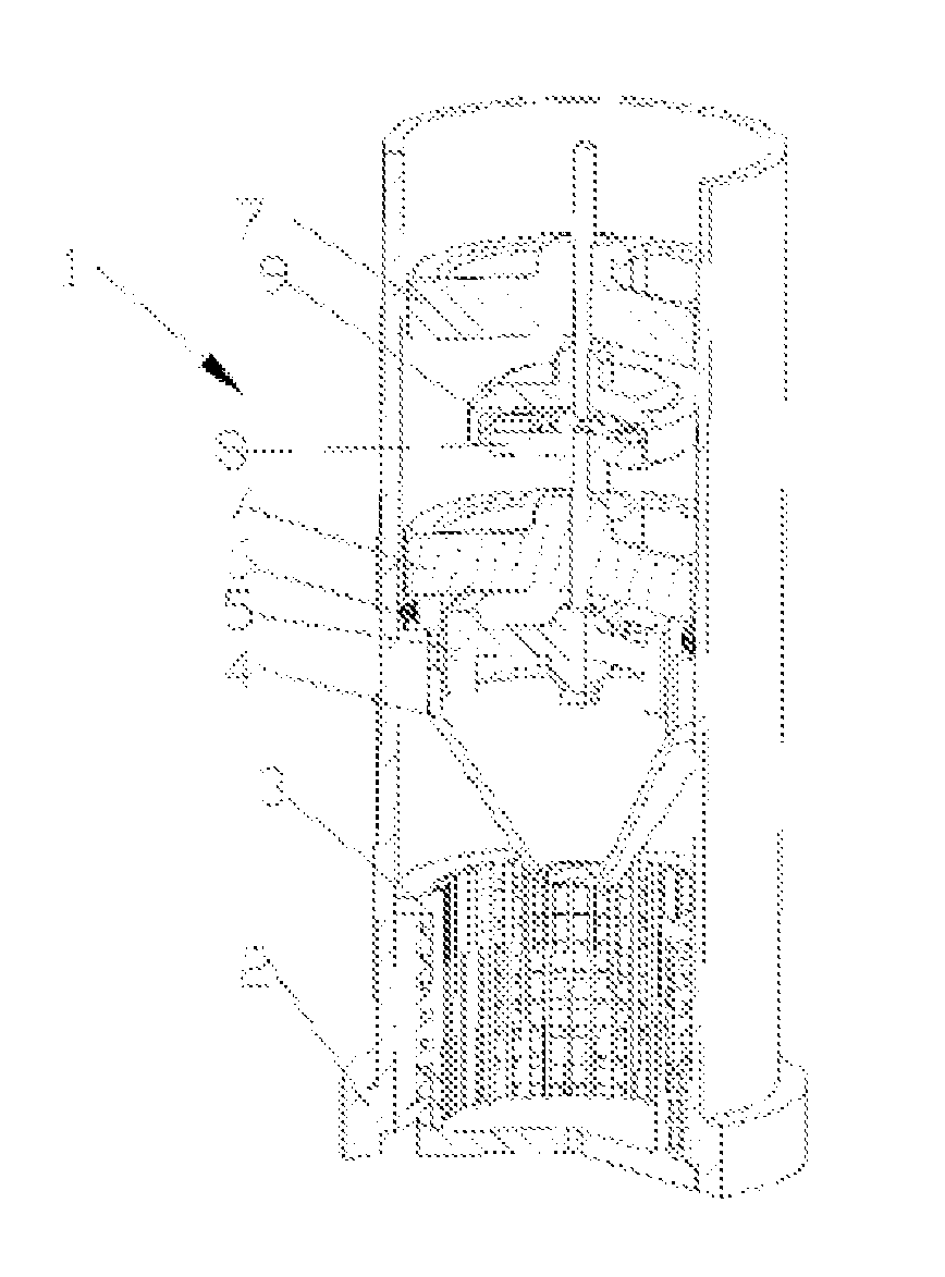
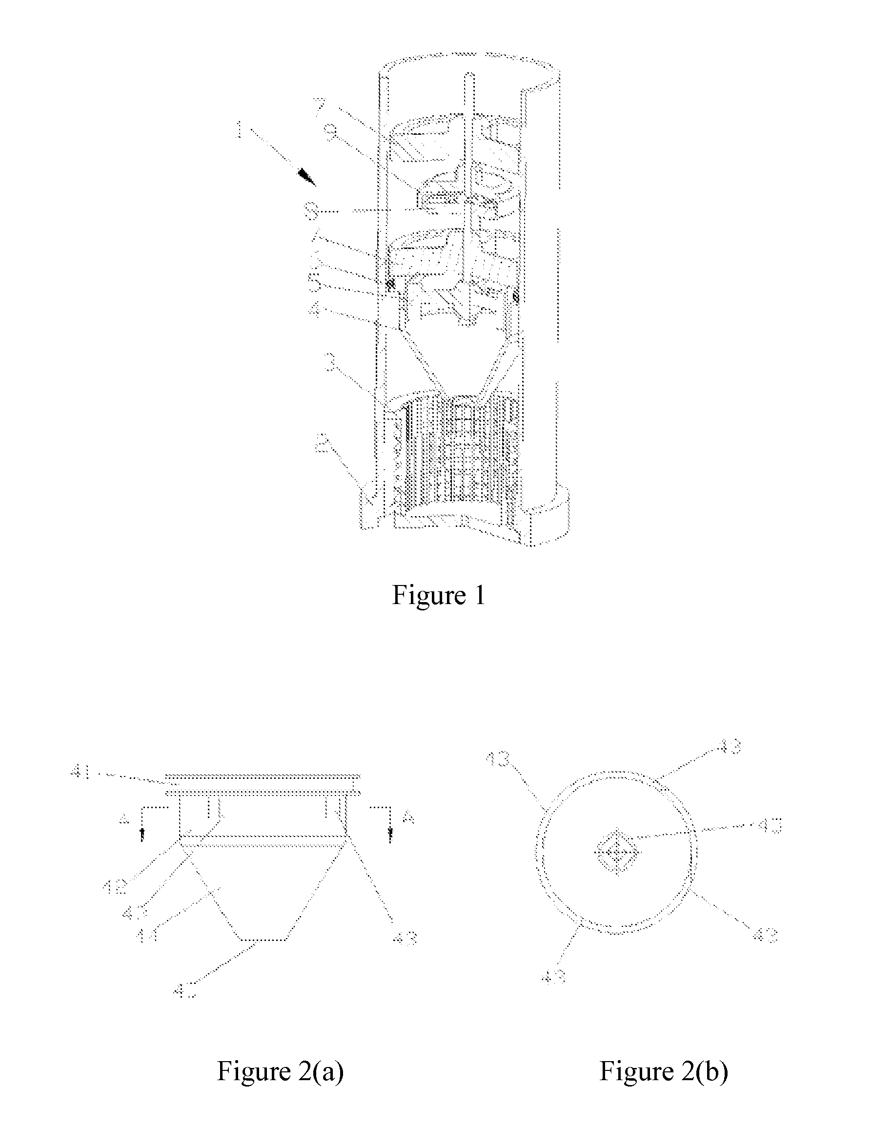
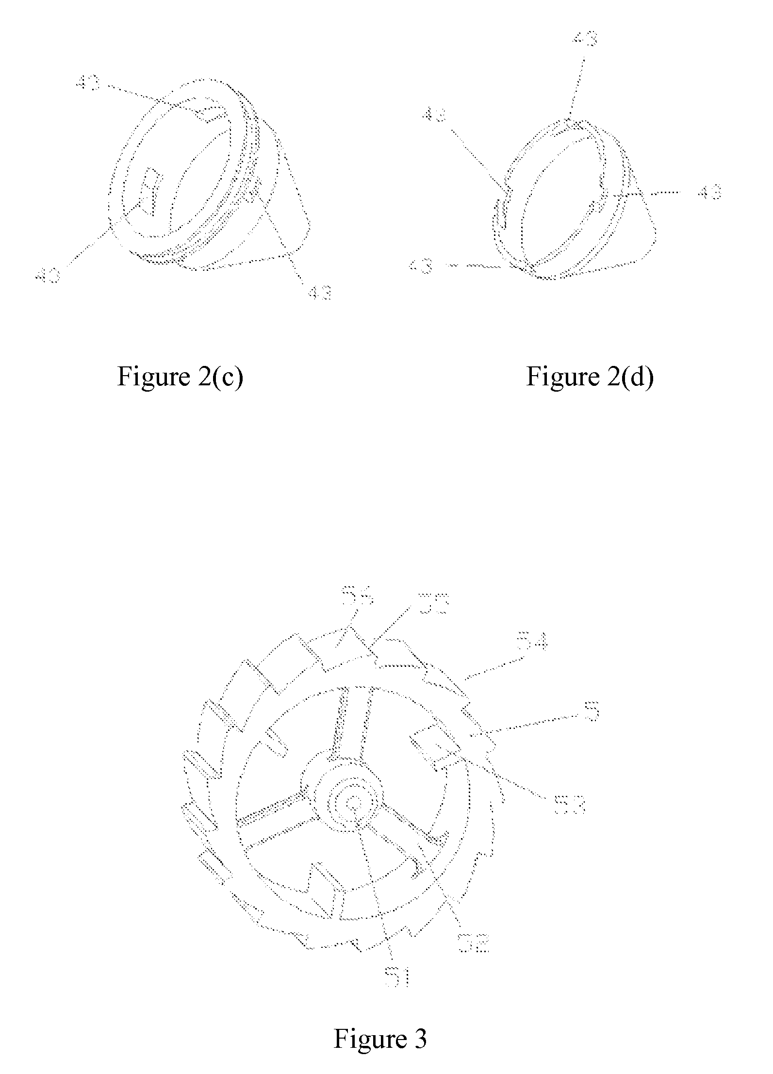
[0026]Referring to FIG. 1, the driving device comprises a case 2, a filter 3, a tangential flow generator 4, a hydraulic rotator 5, a sealing ring 6, a bracket 7, a hydraulic driving disc 8 and a nozzle driving disc 9. The specific installation structure is as follows: the filter 3 is mounted at the inlet of the case 2, the tangential flow generator 4 is positioned downstream of the filter 3, the hydraulic rotator 5 is mounted inside the tangential flow generator 4, the sealing ring 6 is mounted on the tangential flow generator 4 and forms a sealing surface with the inner wall of the case 2, the hydraulic driving disc 8 is fixedly connected with the hydraulic rotator 5 by a shaft and positioned downstream of the hydraulic rotator 5, the shaft is fixed on the inner wall of the case 2 via a bracket 7, the nozzle driving disc 9 is mounted downstream of the hydraulic driving dis...


PUM


Abstract

A driving device for a lifting buried spraying head includes a case (2), a filter (3) provided in the lower end of the case (2), and a spraying head driving unit disposed inside the case (2). The spraying head driving unit connects with a spraying head located on the top end of the case via a main shaft, and the spraying head driving unit drives the spraying head to rotate and spray water. Wherein, the spraying head driving unit comprises a tangential flow generator (4) and a hydraulic rotator (5). The tangential flow generator (4) is a small case structure which is hollow, and a water supply gap is formed between the tangential flow generator and the inner wall of the case (2). Inflow openings (44) are arranged on the shell wall of the tangential flow generator (4). The hydraulic rotator (5) is disposed inside the tangential flow generator (4), and the hydraulic rotator (5) has stress surfaces (55) corresponding to the inflow openings (44). The hydraulic rotator (5) connects with the spraying head directly or indirectly via the main shaft.

Description

FIELD OF THE INVENTION[0001]The invention relates to the field of water-saving irrigation fitting structures, in particular to a hydraulic driving device for a hydraulic lifting buried spaying head.BACKGROUND OF THE INVENTION[0002]Currently, injection pipe technology is adopted to meet water use requirements of places with high water consumption, such as urban green spaces, golf courses, etc. The traditional injection pipe product is complex in structure, having the structure that filtered water rushes at a multi-piece airfoil impeller positioned on an end surface at a certain angle to drive a main shaft to rotate, and a driving gear provided on the main shaft drives a nozzle to rotate after multi-grade gear pair deceleration, achieving the object of spraying. In this driving structure, excess gear pairs brings high difficulty for manufacture and assembly; especially high rotating speed of the driving gear requires high mounting accuracy of each gear shaft and high manufacturing acc...

Claims


Application Information

Patent Timeline
Patent Type & Authority Applications(United States)
IPC IPC(8): B05B3/04
CPCB05B15/062B05B3/0418B05B15/622
Inventor YANG, JIYUEHUANG, HONGBIN
Owner GUANGDONG LIANSU TECH INDAL
Why Eureka
Try Eureka