
Braking control method for electric vehicle

a technology of electric vehicles and control methods, applied in the direction of brake systems, braking components, transportation and packaging, etc., can solve the problems of sudden limitation of charging power (i.e., regenerative braking), limited battery charging by the motor, and reduced regenerative braking capacity, so as to reduce the amount of regenerative braking and increase the amount of hydraulic braking

Inactive Publication Date: 2012-03-08
HYUNDAI MOTOR CO LTD
View PDF7 Cites 44 Cited by
  • Summary
  • Abstract
  • Description
  • Claims
  • Application Information

AI Technical Summary

Benefits of technology

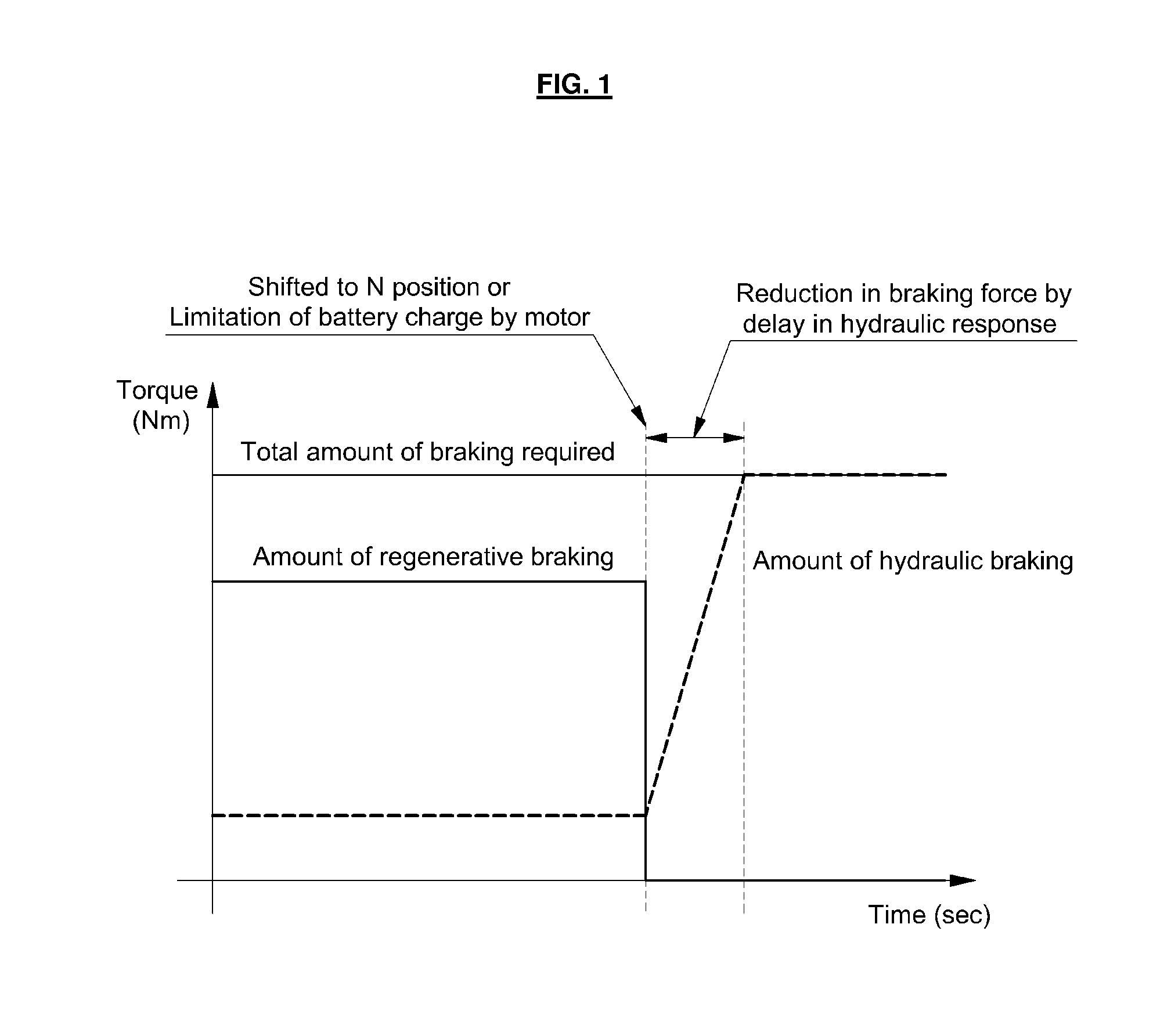
[0021]According to one aspect of the present invention, there is featured a braking control method for an electric vehicle. Such a method includes detecting a position of shift lever to neutral (N) during regenerative braking; linearly reducing the amount of regenerative braking of a motor at a time when the manipulation of the shift lever to the N position is detected and, at the same time, increasing the amount of hydraulic braking of a hydraulic braking system to compensate for the amount of braking; and allowing the shift lever to be shifted to the N position after a predetermined time has elapsed from the time when the manipulation of the shift lever to the N position is detected.
[0023]In another embodiment, the methods of the present invention further includes: determining whether the temperature of the motor or battery has increased to a predetermined reference temperature-2 during regenerative braking; and linearly reducing the amount of regenerative braking of the motor and, at the same time, increasing the amount of hydraulic braking of the hydraulic braking system to compensate for the amount of braking, if the temperature of the motor or battery is determined to have reached the reference temperature-2.
[0026]In further aspects / embodiments of the present invention there is feature another braking control method for an electric vehicle. Such a method includes identifying a vehicle operational condition occurring during regenerative braking or a braking operation of the electric vehicle and that reduces regenerative braking capacity. In such a case, the methods further includes linearly reducing the amount of regenerative braking of a motor of the electric vehicle after identifying such a vehicle operational condition, and at the same time, increasing the amount of hydraulic braking of a hydraulic braking system to compensate for the reducing of the amount of regenerative braking.
[0027]In further embodiments, the operational condition being identified corresponds to the detection of a position of shift lever in neutral (N) during regenerative braking. Such methods further include linearly reducing the amount of regenerative braking of a motor at a time when the manipulation of the shift lever to the N position is detected, and allowing the shift lever to be shifted to the N position after a predetermined time from the time when the manipulation of the shift lever to the N position is detected.

Problems solved by technology

Also, the charging of the battery by the motor is limited in the case, where the shift lever is shifted to Neutral (N) position by a driver during regenerative braking.
(1) When a sudden power limitation is caused (i.e., the regenerative braking torque of the motor is limited) as the temperature of the motor or battery is increased above a predetermined level during regenerative braking; and
(2) When the shift lever is shifted from the Drive (D) position to the neutral (N) position by a driver during braking (i.e., when the motor shaft and the axle are physically separated).
In a typical electric vehicle, when the temperature of the motor or battery is increased above a predetermined level, the charging power (i.e., regenerative braking) is suddenly limited.
Further, in the case where the motor shaft and the axle are physically separated, i.e., when the shift lever is shifted to the N position during braking, the regenerative braking force by the motor cannot be transmitted to the vehicle as deceleration torque.
However, the hydraulic response of the hydraulic braking system is not fast enough to compensate for the sharp reduction in regenerative braking, and thus the braking force is reduced by the delay in hydraulic response.

Method used


Image

  • Braking control method for electric vehicle
  • Braking control method for electric vehicle
  • Braking control method for electric vehicle

Examples


Embodiment Construction

[0040]Hereinafter reference will now be made in detail to various embodiments of the present invention, examples of which are illustrated in the accompanying drawings and described below. It is will be understood that the following present description is not intended to limit the scope of the present invention to those exemplary embodiments. It shall be understood that the scope of the invention shall embrace various alternatives, modifications, equivalents and other embodiments, which may be included within the spirit and scope of the invention as defined by the appended claims.

[0041]The present invention provides or features a braking control method for an electric vehicle. Such braking control methods advantageously address the shortcomings of conventional methods concerning the reduction in braking force caused by a sharp reduction in the amount of regenerative braking and a delay in hydraulic response under conditions where the regenerative braking by a motor (i.e., drive motor...


PUM


Abstract

The present invention features braking control methods for an electric vehicle. Such methods include identifying a vehicle operational condition occurring during regenerative braking that reduces regenerative braking capacity; linearly reducing the amount of regenerative braking of a motor of the electric vehicle after identifying such a vehicle operational condition; and at the same time, increasing the amount of hydraulic braking of a hydraulic braking system to compensate for the reducing of the amount of regenerative braking. Such operational conditions include when the temperature of a motor or battery is increased above a predetermined level during regenerative braking or when the shift lever is shifted to Neutral (N) position by a driver during regenerative braking.

Description

CROSS-REFERENCE TO RELATED APPLICATION[0001]This application claims under 35 U.S.C. §119(a), priority to and the benefit of Korean Patent Application No. 10-2010-0086506 filed Sep. 3, 2010, the entire contents of which are incorporated herein by reference.BACKGROUND[0002]1. Technical Field[0003]The present invention generally relates to a braking control method for an electric vehicle. More particularly, the present invention relates to a braking control method for an electric vehicle, which effectively handles reduction in braking force caused by a sharp reduction in the amount of regenerative braking and a delay in hydraulic response. More specifically, such a backing control method when the temperature of a motor or battery is increased above a predetermined level or when the shift lever is shifted to Neutral (N) position by a driver, in which regenerative braking by the motor is impossible.[0004]2. Background Art[0005]A hybrid vehicle, in a broad sense is a vehicle driven by eff...

Claims


Application Information

Patent Timeline
Patent Type & Authority Applications(United States)
IPC IPC(8): B60T13/74B60L7/24B60L7/26B60T13/58
CPCB60L7/18B60W2710/182B60T1/10B60T13/586B60T13/662B60T2270/604B60W10/08B60W10/188B60W30/18127B60W30/1843B60W2510/087B60W2510/244B60W2510/246B60W2540/12B60W2540/16B60W2710/083B60L7/26
Inventor KIM, SANG JOON
Owner HYUNDAI MOTOR CO LTD
Learn More