Roller wheel for track-type travelling vehicle

a technology of rolling wheel and travelling vehicle, which is applied in the direction of hoisting equipment, mechanical control devices, instruments, etc., can solve the problems of uneven contact between the shaft and the bumping, and achieve the effect of easy deformation, easy deformation in the fitting, and easy deformation

Inactive Publication Date: 2012-03-08
KOMATSU LTD
View PDF12 Cites 23 Cited by
  • Summary
  • Abstract
  • Description
  • Claims
  • Application Information

AI Technical Summary

Benefits of technology

[0023]A roller wheel for a track-type travelling vehicle according to an eighth aspect of the present invention relates to the roller wheel for a track-type travelling vehicle according to the seventh aspect of the present invention. In the roller wheel, each of the protrusions of the inner and outer roller shells is tapered. The outer diameter of each of the protrusions is increased in proportion to distance from the other of the inner and outer roller shells.
[0024]According to the roller wheel of the eighth aspect of the present invention, each protrusion is tapered. Therefore, the coupling ring can be easily fitted onto the respective inner and outer roller shells.
[0025]A roller wheel for a track-type travelling vehicle according to a ninth aspect of the present invention relates to the roller wheel for a track-type travelling vehicle according to the eighth aspect of the present invention. In the roller wheel, each of the inner and outer roller shells includes the protrusion continuously on the entire circumference ...

Problems solved by technology

However, the bushings and the shaft unevenly make contact with each other when the inn...

Method used


Image

  • Roller wheel for track-type travelling vehicle
  • Roller wheel for track-type travelling vehicle
  • Roller wheel for track-type travelling vehicle

Examples


first exemplary embodiment

Modification of First Exemplary Embodiment

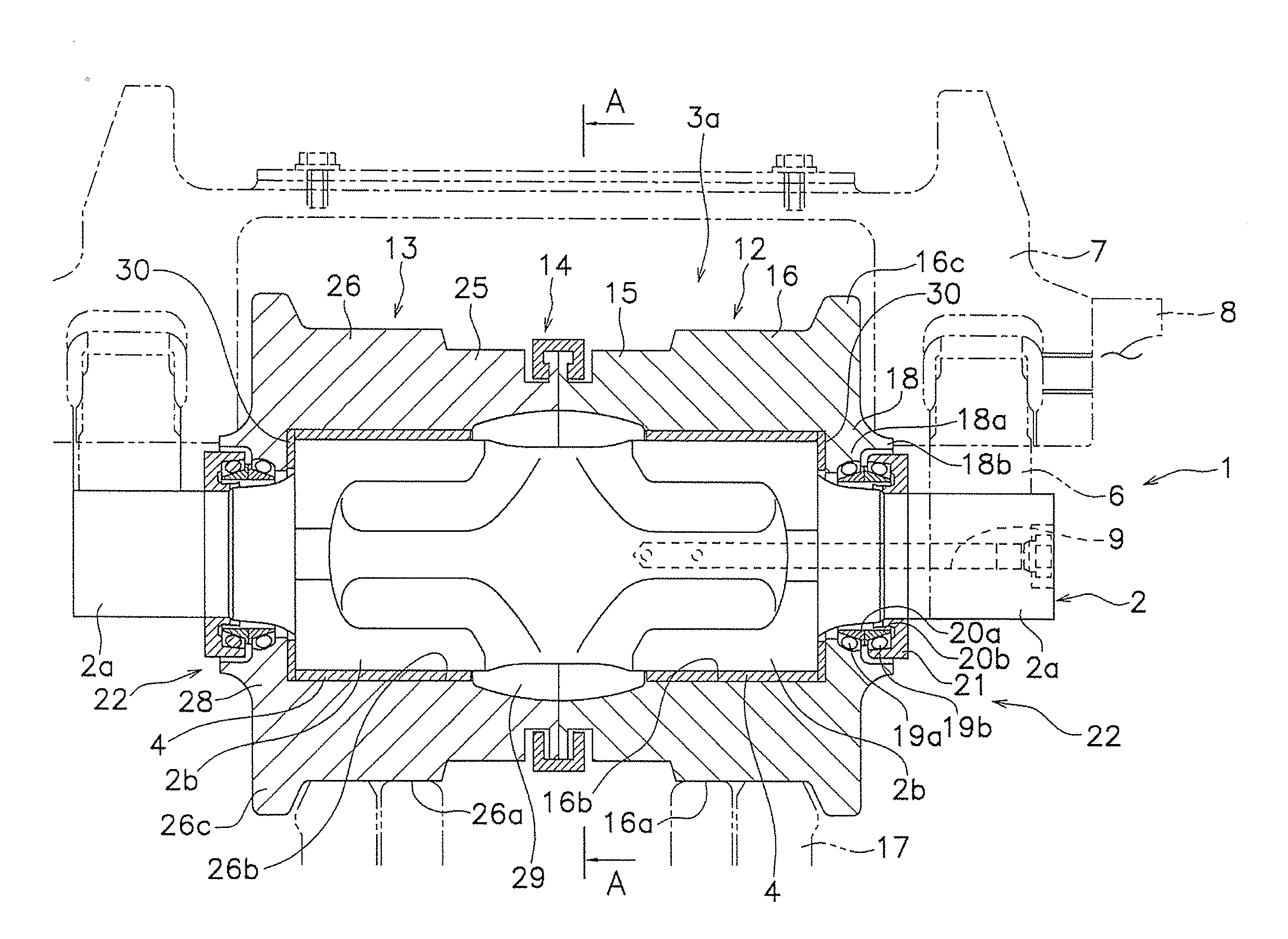
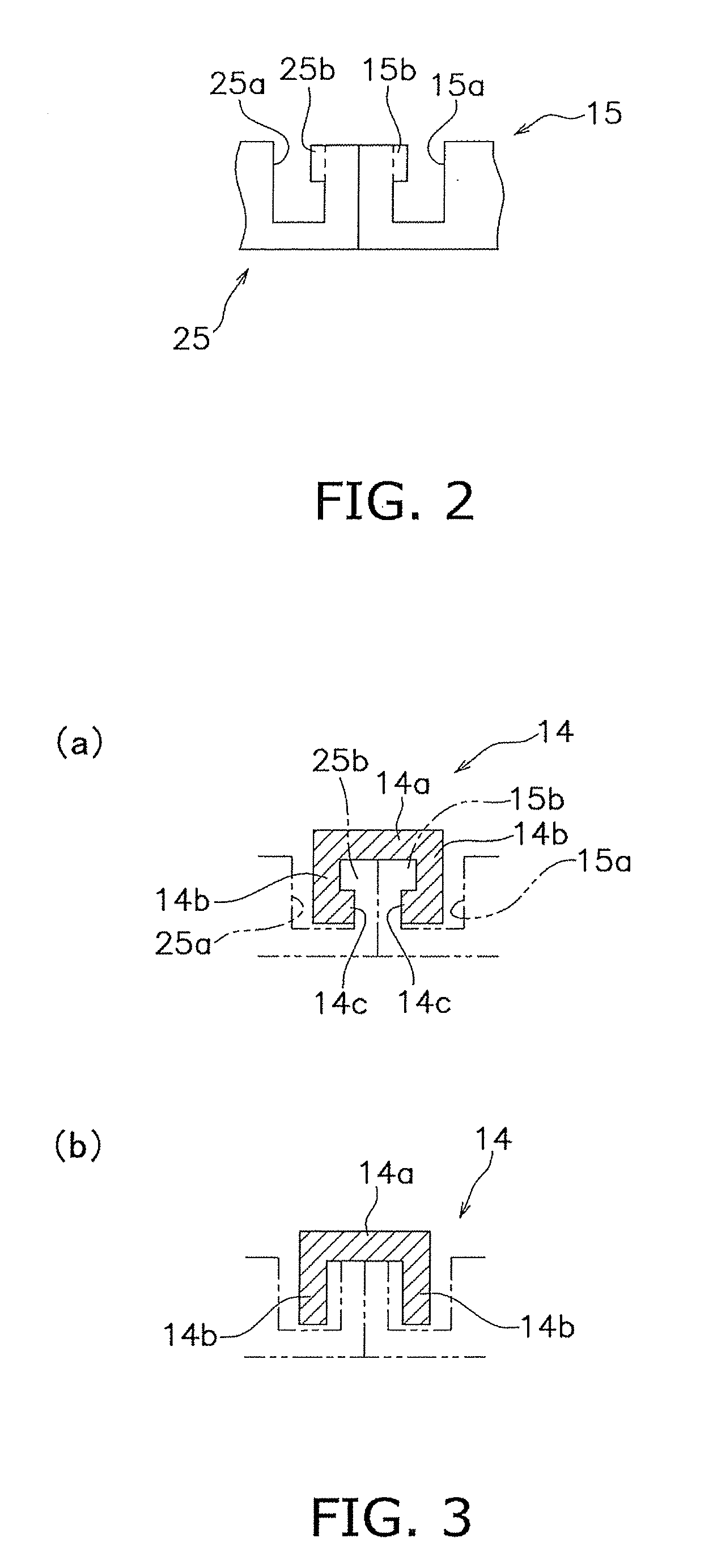
[0088](a) The shapes and the number of the engaging portion of the coupling ring 14, the annular grooves and the protrusions formed in each of the inner and outer roller shells 12 and 13 are not limited to those in the aforementioned exemplary embodiment. For example, the coupling ring 14 may include three or more engaging portions. Further, either or both of each protrusion and each engaging portion may include a circumferentially slanted surface(s). Accordingly, when being rotated and attached to the roller shells, the coupling ring (i.e., the split rings) may be configured to be rigidly fixed thereto in accordance with rotation thereof.

[0089](b) As illustrated in FIG. 6, two split rings may be coupled by means of pins. In the example illustrated in FIG. 6, a split ring 32, which is one of the two split rings 32 and 33, includes an engaging notch 32a on the inner peripheral part of each circumferential end thereof. Further, the split ring ...

second exemplary embodiment

Modification of Second Exemplary Embodiment

[0107](a) The shapes of the protrusions and the coupling ring are not limited to those of the second exemplary embodiment. For example, as illustrated in FIG. 13, a coupling ring 44′ may be formed as a C-shaped snap ring having an axial slit 44a′. In this case, the coupling ring 44′ can be easily expanded when being engaged with the protrusions 47 and 57 of the inner and outer roller shells 42 and 43. Thus, the roller assembly can be easily attached onto the shaft.

[0108]Further, the slit shape is not limited to that illustrated in FIG. 13. For example, the coupling ring 44′ may include a plurality of slits on the both axial ends thereof. Each slit herein has a short axial length and thereby does not reach the other axial end. In this case, the coupling ring 44′ is formed as an O-shaped ring.

[0109](b) As another modification of the second exemplary embodiment, the convex-concave fitting and the sealing structure can be also employed as illus...

third exemplary embodiment

Modification of Third Exemplary Embodiment

[0129](a) The interlocking protrusion formed in the inner roller shell 112 may be formed in the outer roller shell 113 while the interlocking groove formed in the outer roller shell 113 may be formed in the inner roller shell 112.

[0130](b) As illustrated in FIG. 16, the inner roller shell 112 may include a plurality of axial slits 115d in the inner interlocking portion 115 for further easily achieving elastic deformation of the inner interlocking portion 115.

[0131](c) Arrangements of the annular sealing groove and the sealing member are not limited to those of the third exemplary embodiment. For example, the faced edges of the inner and outer roller shells 112 and 113 may be abutted to each other. Further, either or both of the edges may include an annular sealing groove and a sealing member may be disposed therein.

Fourth Exemplarly Embodiment

Structure

[0132]FIG. 17 illustrates a roller wheel according to a fourth exemplary embodiment of the ...


PUM


Abstract

A roller wheel for a track-type travelling vehicle is disposed on a non-ground-engaging side of a track and supported by a vehicle body frame. The roller wheel includes a shaft, a roller assembly and a bearing. The shaft is supported by the vehicle body frame. The roller assembly is disposed on an outer periphery of the shaft. The bearing allows the roller assembly to be rotatably supported by the shaft therethrough. The roller assembly includes a tubular inner roller shell disposed closer to the vehicle body frame, and a tubular outer roller shell disposed outwards of the inner roller, the tubular outer roller shell being coupled to the inner roller shell by a straddle fitting structure.

Description

CROSS-REFERENCE TO RELATED APPLICATIONS[0001]This national phase application claims priority to Japanese Patent Application No. 2009-131815 filed on Jun. 1, 2009. The entire disclosure of Japanese Patent Application No. 2009-131815 is hereby incorporated herein by reference.FIELD OF THE INVENTION[0002]The present invention relates to a roller wheel for a track-type travelling vehicle, and particularly to, a roller wheel for a track-type travelling vehicle, which is supported by a vehicle body frame while being disposed on a non-ground-engaging side of a track (crawler belt).BACKGROUND ART[0003]The track-type travelling vehicles (also referred to as crawler-type travelling vehicles) have been popular as vehicles, such as bulldozers and hydraulic excavators, mainly used for works on irregular terrain. In the track-type travelling vehicles, a drive unit includes two pairs of a driving wheel and an idler tumbler on the transverse sides thereof. The driving wheel and the idler tumbler on...

Claims


Application Information

Patent Timeline
IPC IPC(8): B62D55/14
CPCB62D55/0887B62D55/32B62D55/15B62D55/14
Inventor HASHIMOTO, AKIRAYAMASHITA, TATSUONAKAISHI, HIROYUKI
Owner KOMATSU LTD
Why Eureka
Try Eureka