Image display apparatus

a technology of image display and display screen, which is applied in the direction of projectors, color television details, instruments, etc., can solve the problems of image display apparatus and inability to operate, and achieve the effect of compactness and effective utilization of the space inside the image display apparatus

Inactive Publication Date: 2012-03-08
PANASONIC CORP
View PDF2 Cites 14 Cited by
  • Summary
  • Abstract
  • Description
  • Claims
  • Application Information

AI Technical Summary

Benefits of technology

[0009]An advantage of the present invention is to provide an image display apparatus that compact enough to be installed in an electronic device.
[0010]The image display apparatus according to the present invention has: a case that is distinguished into a plurality of regions and has a projection port; an image display apparatus main body that projects an image from the projection port; and a controller that electrically connects to the image display apparatus main body and to an external electronic device, and is positioned so as to straddle on the plurality of regions. The case includes: a first region that houses a first portion of the controller and is held by the electronic device at least at one portion of the region; a second region that is positioned away from the electronic device so as to sandwich the first region and houses the image display apparatus main body; and a third region that is positioned away from the projection port and away from the electronic device so as to sandwich the first region, and houses a second portion of the controller.
[0011]Accordingly, the image display apparatus main body and the electronic device are electrically connected via the controller. Thus, electricity is supplied from the electronic device to the image display apparatus main body. Further, the electronic device can project an image from the image display apparatus main body via the controller. Therefore, without being hard-wired outside to the electronic device, an image to be displayed by the electronic device can be projected.
[0012]In addition, since the electronic device holds at least a portion of the first region, the image display apparatus is held by the electronic device. The second and third regions positioned beyond the first region away from the electronic device protrude outside the electronic device. Therefore, image display apparatus main body provided in the second region can project an image from the projection port of the second region.
[0013]The controller is positioned so as to straddle on the first and third regions, thereby effectively utilizing the space inside the image display apparatus. Accordingly, the image display apparatus can be made compact.
[0014]Another aspect of the present invention is to adjust the projection angle of the image display apparatus, i.e., to adjust the position if the image to be projected. Accordingly, the second region of the case rotates in a direction perpendicular to a direction to which the image display apparatus projects an image.

Problems solved by technology

In the conventional image display apparatus, however, cannot be operated unless the power source is secured by itself.

Method used


Image

  • Image display apparatus
  • Image display apparatus
  • Image display apparatus

Examples


embodiment 1

[0030]Hereinafter, embodiment 1 of the present invention will be explained with reference to the drawings.

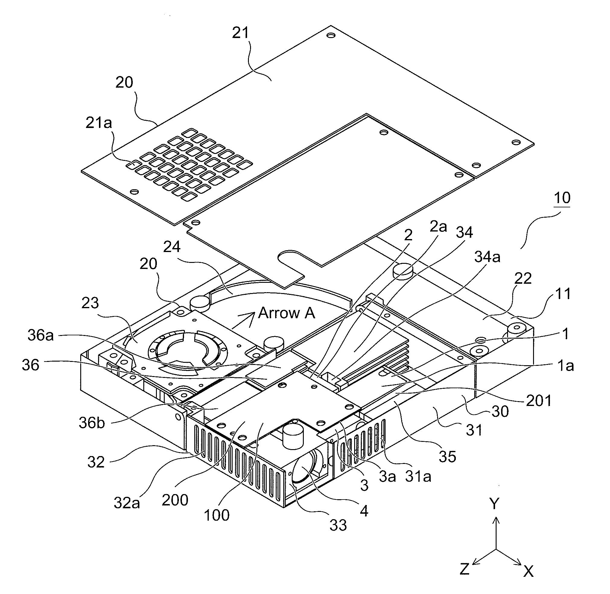
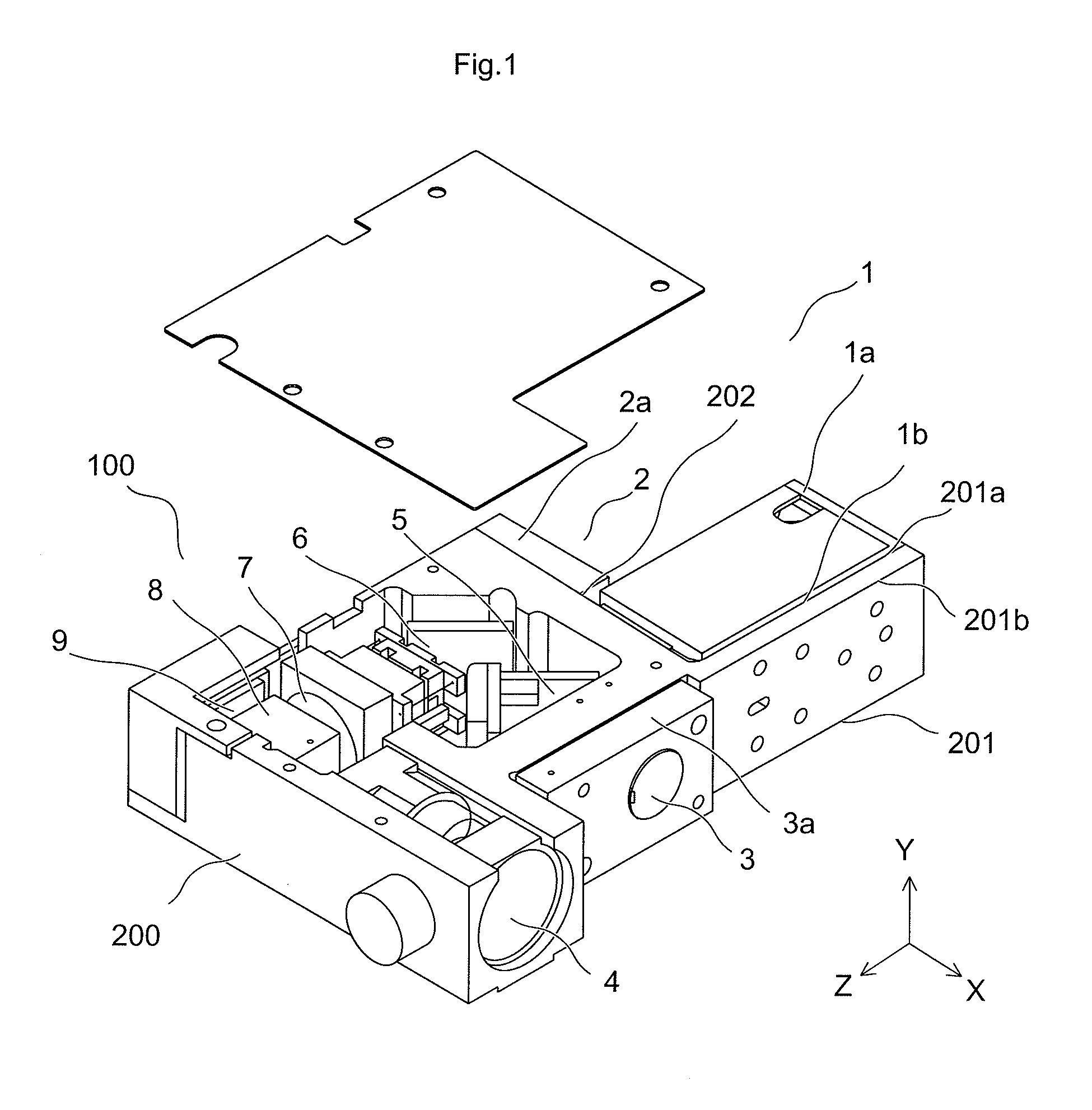
[0031]First, the configuration of the image display apparatus main body will be explained with reference to FIG. 1. FIG. 1 is a schematic perspective view of the image display apparatus main body according to the embodiment 1 of the present invention.

[0032]In FIG. 1, the image display apparatus main body 100 uses laser light as a light source and performs magnification and projection on the screen. The image display apparatus main body 100 has three light sources, that is, a green color laser light source apparatus 1, a red color laser light source apparatus 2, and a blue color laser light source apparatus 3. The image display apparatus main body 100 displays an image with the three-color laser light source apparatuses 1-3.

[0033]The green color laser light source apparatus 1 mainly outputs green color laser light by converting non-visible infrared fundamental laser light to a ha...

embodiment 2

[0107]Embodiment 2 of the present invention is hereinafter described with reference to FIG. 9. FIG. 9 illustrates an example of a cooling air passage of the image display apparatus according to the embodiment 2 of the present invention. Component members having the same configuration and function as the embodiment 1 will be given the same numerical references and the detailed illustration thereof will be omitted.

[0108]The arranged location of the cooling fan 23, arrangement of and configuration of the control base, and arrangement and configuration of the fin in the embodiment 2 are different from the embodiment 1. The differences are described hereafter in detail.

[0109]As shown in FIG. 9, the cooling fan 23 is provided in an opposite direction of the arrow X away from the opening 38, and ejects cooling air in a direction of an arrow G. Therefore, in this embodiment, the guide 24 is not provided. The cooling air from the cooling fan 23 directly cools the fin 34. Although not shown i...


PUM


Abstract

Provided is an image display apparatus that has: a case distinguished into a plurality of regions and has a projection port; an image display apparatus main body that projects an image from the projection port; and a controller that electrically connects to the image display apparatus main body and to an external electronic device, and is positioned so as to straddle on the plurality of regions. The case has: a first region that houses a first portion of the controller and is held by the electronic device at least at one portion of the region; a second region positioned away from the electronic device so as to sandwich the first region and houses the image display apparatus main body; and a third region positioned away from the projection port and away from the electronic device so as to sandwich the first region, and houses a second portion of the controller. Therefore, the image display apparatus can be made compact to be installed within an electronic device.

Description

CROSS-REFERENCE TO RELATED APPLICATIONS[0001]The present application claims priority under 35 U.S.C. §119 of Japanese Application No. 2010-196384, filed on Sep. 2, 2010, the disclosure of which is expressly incorporated by reference herein in its entirety.BACKGROUND OF THE INVENTION[0002]1. Field of the Invention[0003]The present invention relates to an image display apparatus in which a laser light source apparatus using a semiconductor laser is incorporated.[0004]2. Description of Related Art[0005]In recent years, laser light has drawn attention as a light source of an image display apparatus which can perform large-screen display, and technology development of a semiconductor laser has been promoted to form this laser light. Compared with a ultra-high pressure mercury lamp (UHP lamp) conventionally used as a light source of an image display apparatus or a light-emitting diode (LED) recently used in a small-sized image display apparatus, a light source using a semiconductor laser ...

Claims


Application Information

Patent Timeline
Patent Type & Authority Applications(United States)
IPC IPC(8): G03B21/16G03B21/14
CPCH04N9/3141H04N9/3197H04N9/3161H04N9/3144
Inventor ENOMOTO, HIROFUMISUYAMA, KOHEITESHIMA, YOSHIHIROJIKUYA, NOBUOSATO, KAORU
Owner PANASONIC CORP
Why Eureka
Try Eureka