Biopsy guide system with an ultrasound transducer and method of using same

a technology of ultrasound transducer and biopsy guide, which is applied in the field of biopsy guide system, can solve the problems of not having perfect sharp boundaries of ultrasound beam, no guidance imaging may be available, and complicating matters further, so as to avoid mistakes during the procedure and improve awareness of nearby structures.

Active Publication Date: 2012-03-08
KONINKLIJKE PHILIPS ELECTRONICS NV
View PDF14 Cites 51 Cited by
  • Summary
  • Abstract
  • Description
  • Claims
  • Application Information

AI Technical Summary

Benefits of technology

[0035]According to a further embodiment of the present invention, the 2D matrix ultrasound transducer is adapted to acquire 3D ultrasound images. The ability of a 2D matrix ultrasound transducer to acquire ultrasound images from a volume may allow for the ability of deriving 3D ultrasound images. Thereby, it is possible to provide a 3D or volume representation of a region of interest. Such 3D representation may even be time-dependent (sometimes referred to as “live 3D ” or “4D”) by concatenating a plurality of 3D representations acquired in a time sequence. Biopsy needles may be guided within an acquired 3D image. Biopsy guidance in live 3D may provide better awareness of nearby structures and may thereby help to avoid mistakes during the procedure.
[0036]A biopsy arrangement comprising a multi-position biopsy guide system as described above and further comprising a display device for displaying ultrasound images acquired by the 2D matrix ultrasound transducer may be used to assist a physician in finding a region of interest and/or monitoring the guidance of a biopsy needle towards the region o

Problems solved by technology

To further complicate matters, the ultrasound beam does not have perfectly sharp boundaries.
A different needle guide location could be used, but since the biopsy needles pat

Method used


Image

  • Biopsy guide system with an ultrasound transducer and method of using same
  • Biopsy guide system with an ultrasound transducer and method of using same
  • Biopsy guide system with an ultrasound transducer and method of using same

Examples


Embodiment Construction

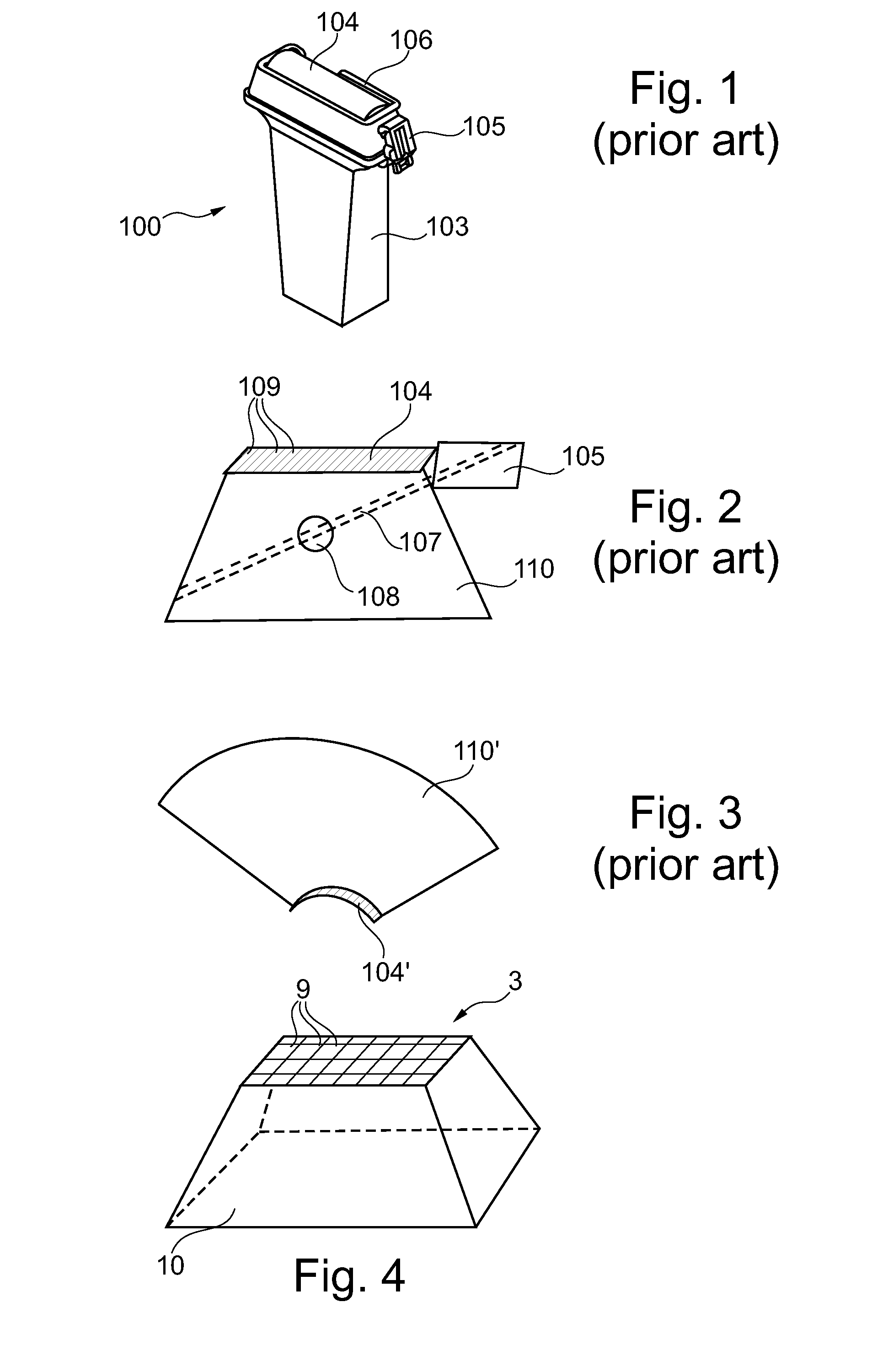
[0051]The conventional biopsy guide system 100 shown in FIG. 1 comprises a 1D ultrasound transducer 103. A biopsy guide bracket 106 is arranged around the transducer face 104. In an azimuthal position with respect to the longitudinal transducer face 104, a biopsy needle guide 105 is attached to the biopsy guide bracket 106. As indicated in FIG. 2, the ultrasound transducer 103 with the one-dimensional transducer face 104 is adapted to acquire an image from within a trapezoidal region included in an image plane 110 coinciding with and orthogonal to the transducer face 104.

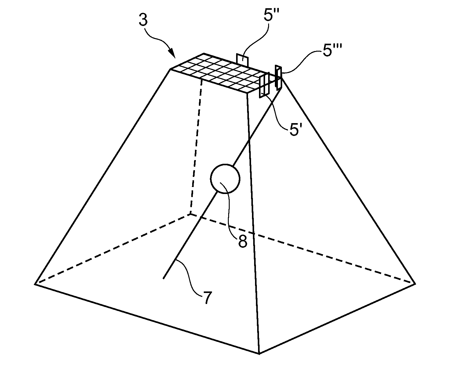
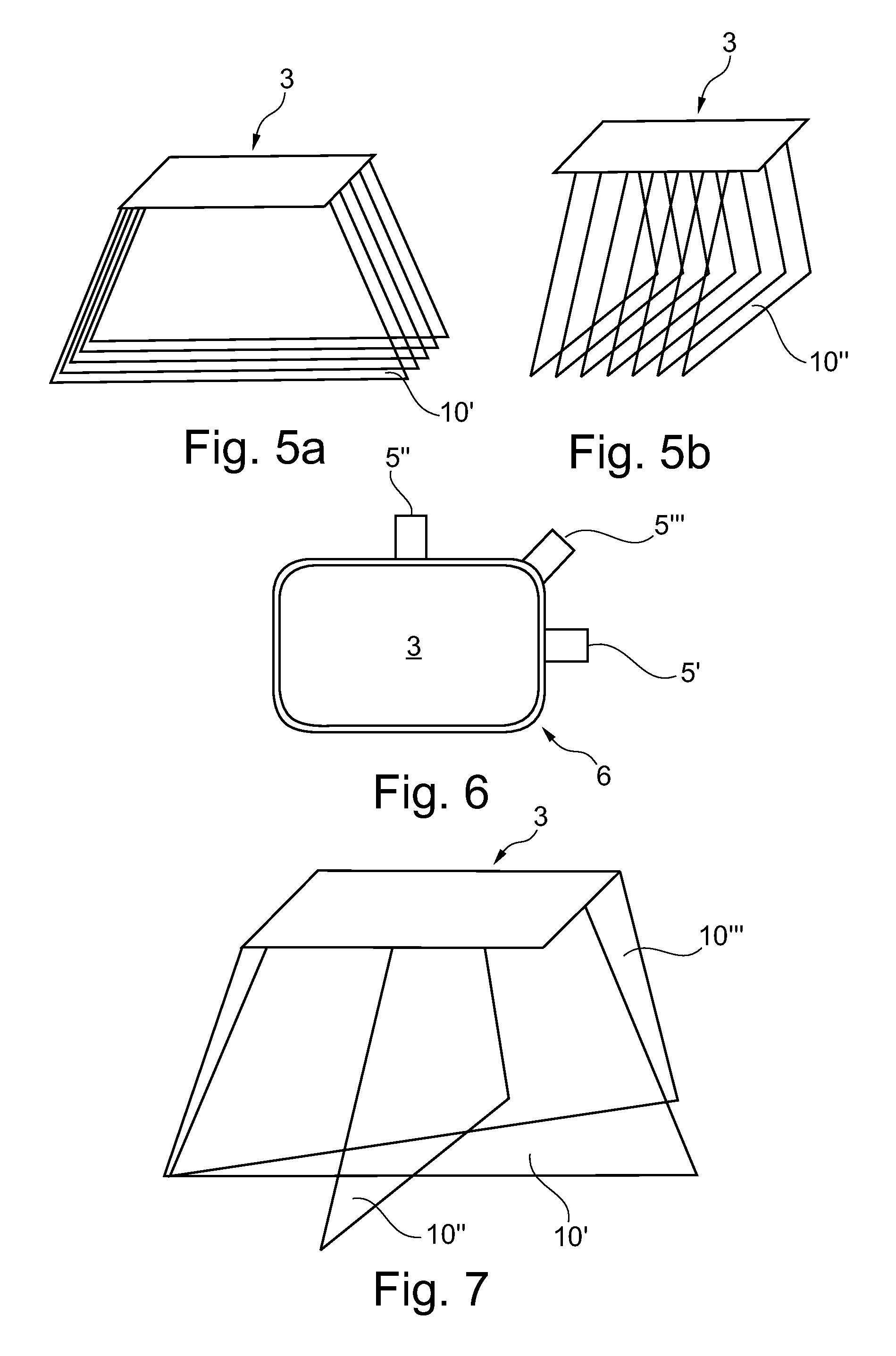
[0052]While with the conventional biopsy guide system shown in FIGS. 1 and 2 the image plane 110 has to be moved together with the biopsy guide system until it coincides with a region of interest 108 such that a biopsy needle may be guided along a biopsy path 107 using the biopsy needle guide 105, FIG. 4 illustrates an advantage which may be obtained when using a two-dimensional matrix ultrasound transducer for the ...


PUM


Abstract

A multi-position biopsy guide system and a method of using such biopsy guide system is proposed. The biopsy guide system comprises a 2D matrix ultra-sound transducer (3) and comprises at least one biopsy needle guide (5) adapted for guiding a biopsy needle along a biopsy path (7). Therein, the multi-position biopsy guide system is adapted to controllably guide the biopsy needle along biopsy paths at variable locations with respect to the 2D matrix ultrasound transducer. Preferably, a location of the biopsy needle guide (5) with respect to the matrix ultrasound transducer may be determined and an ultrasound image in an image plane aligned with a biopsy path corresponding to the determined location of the biopsy needle guide may be acquired. Thereby, a biopsy process may be monitored for various locations and orientations of a guided biopsy needle.

Description

FIELD OF THE INVENTION[0001]The invention relates to a biopsy guide system for guiding a biopsy needle along a biopsy path while monitoring with an ultrasound transducer. Furthermore, the invention relates to a method of controlling guidance of a biopsy needle using such biopsy guide.BACKGROUND OF THE INVENTION[0002]A biopsy is a medical test involving the removal of cells or tissues from a region of interest such as a lesion for medical examination purposes. The removed cells or tissues may be examined in order to detect the presence or extent of a disease.[0003]For removing the cells or tissues, a biopsy needle has to be introduced into a patient's body and has to be guided to the region of interest. In order to enable monitoring of the introduction and guidance of the biopsy needle, ultrasound transducers are frequently used to observe the region of interest during the insertion of the biopsy needle.[0004]As described for example in WO2006 / 060657-A2, a biopsy needle guide adapted...

Claims


Application Information

Patent Timeline
IPC IPC(8): A61B10/02A61B8/14
CPCA61B8/0833A61B8/0841A61B17/3403A61B8/483G01S7/52073G01S7/52074G01S15/8993A61B2017/3413
Inventor ROBINSON, ANDREW LEE
Owner KONINKLIJKE PHILIPS ELECTRONICS NV
Why Eureka
Try Eureka