
Data integration using conceptual modeling framework

a conceptual modeling and data integration technology, applied in the field of system and method for data integration, can solve the problems of large amount of time, effort and computational resources, and insufficient two-layered relational system to model this complexity, and achieve the effects of avoiding violation, reducing time required, and reducing effor

Active Publication Date: 2012-03-08
TATA CONSULTANCY SERVICES LTD
View PDF1 Cites 17 Cited by
  • Summary
  • Abstract
  • Description
  • Claims
  • Application Information

AI Technical Summary

Benefits of technology

[0017]It is further object of the present invention to translate a query given on global schema into an equivalent source schema by providing a query rewriting approach that guarantees maximal containment of source query in global query.
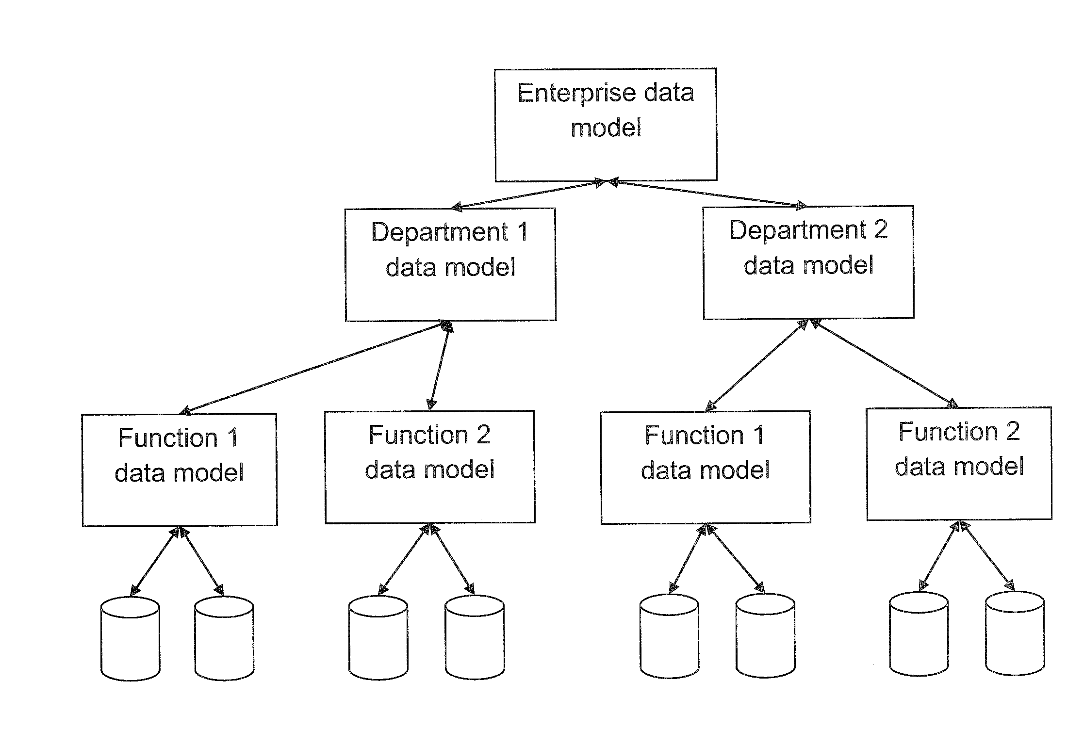
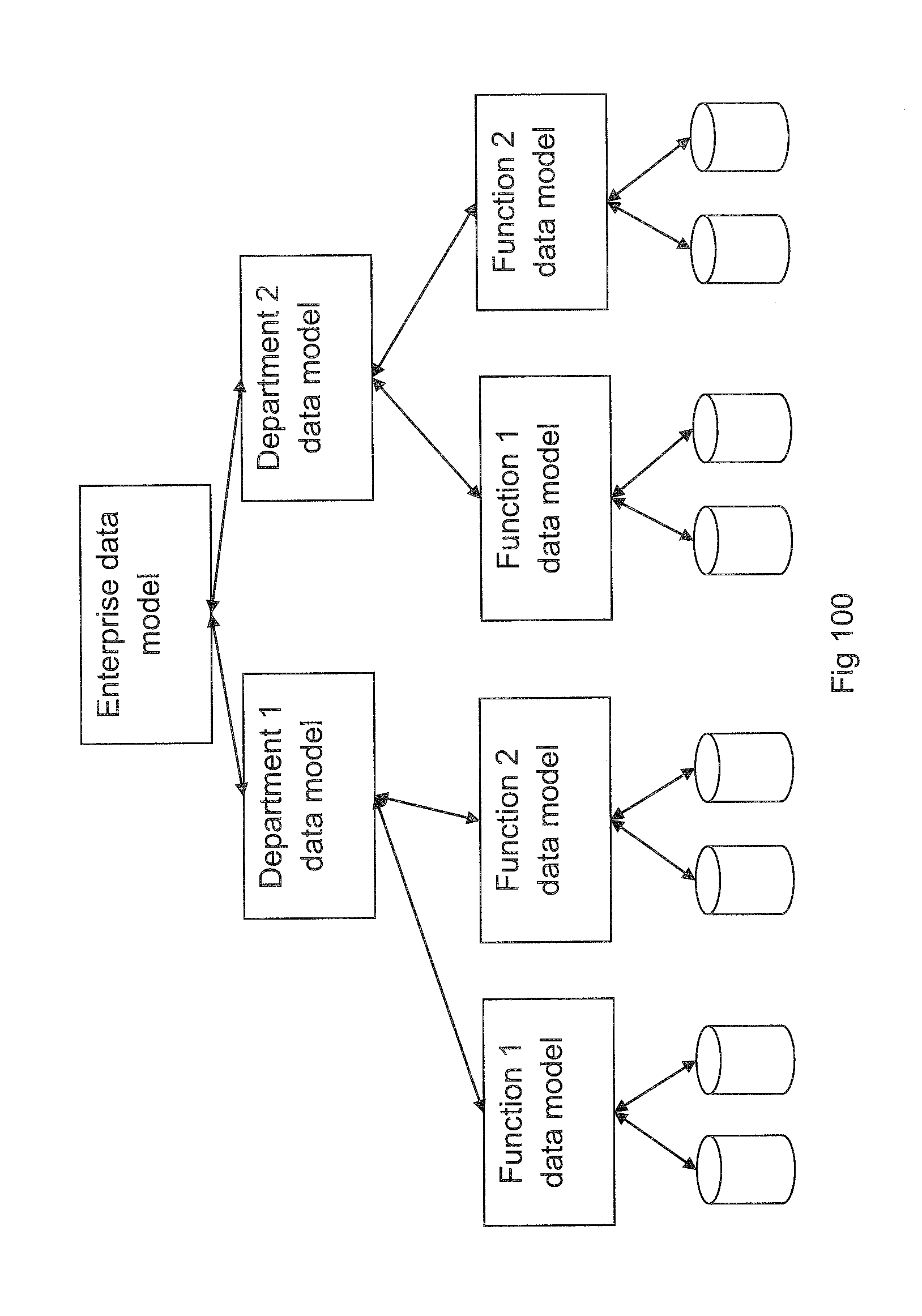
[0019]Another object of the present invention is to minimize the efforts employed in creating and maintaining repository of an organization's electronically stored data at each level of a hierarchy.
[0020]Yet another object of the present invention is to materialize an aggregated view of organizational information at each intermediate level of an enterprise thereby reducing the time required and other latency issues that may occur while retrieving the information existing at various storage locations.
[0021]It is yet another object of the present invention to maintain consistency within different data structures supported by disparately located databases to avoid violation of data integrity constraints that may arise during execution of query initialized by the user.

Problems solved by technology

A two layered relational system is not adequate to model this complexity.
This involves large amount of time, efforts and computational resources at each of these enterprise levels.
Moreover, consistency of the data to be maintained at each of these enterprise levels by way of data synchronization is an added responsibility and burden for the existing systems.
The prior art is however suitable only for mapping between the data models across a single layer and is not suited for mapping between complex data models across an hierarchical level.
Therefore, the existing solutions generally do not provide support for modeling data within real time enterprise application where the complexities of modeling are associated with data existing in a hierarchy.
For a dynamic environment views are often complex and the efforts required in their design are considerable.

Method used


Image

  • Data integration using conceptual modeling framework
  • Data integration using conceptual modeling framework
  • Data integration using conceptual modeling framework

Examples


case 2

f the relations in both Global Schema G and Source Schema S are involved in both GAV and LAV mappings.

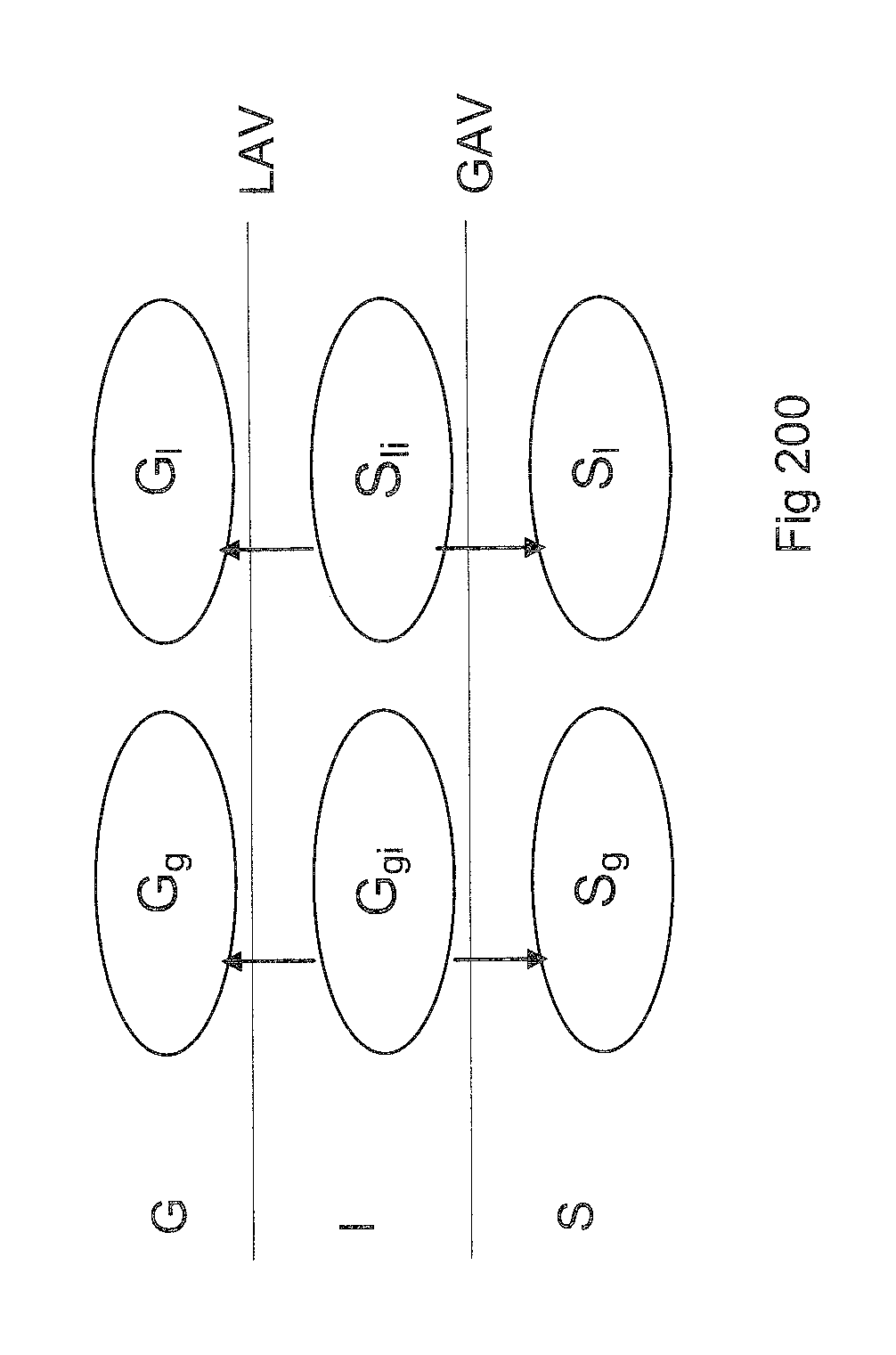
[0081]G is partitioned into three sets Gg, Gl and Ggl. The relations in Ggl participate in both GAV and LAV mappings. Similarly S is grouped into three sets Sg, Sl and Sgl (which are not necessarily mutually exclusive). This can be modeled as shown in FIG. 300, where Gg, Gl, Ggi, Gli, Sg and Sl are as in case 1, and Ggli is a copy of Ggl (with suitable renaming of tables), Sgli is a copy of Sgi (with suitable renaming of tables), with a one-to-one LAV mapping between Ggl and Ggli, original LAV mapping (after suitable renamings) between Ggl and Sgli, original GAV mapping (after suitable renamings) between Ggli and Sgl, and a one-to-one GAV mapping between Sgli and Sgl.

case 3

ting simple inheritance relationships between data entities

[0082]Let's say D={G, Sc, Sr, H, Ml, Mg} is our enhanced integration system

[0083]Where G is the global conceptual model, Sc is the source level conceptual model, Sr is the source level relational schema, H is the inheritance relation (i.e. pairs) over G∪Sc, Ml is the LAV mapping between G and S (i.e. Sc∪Sr), and Mg is the GAV mapping between G and S.

[0084]Now, turn an inheritance relation (i.e. B inherits from A) into the following GAV definition:

A:−B

[0085]If more than one class (say B, C, D, . . . ) inherit from A, we have as many mapping rules:

A:−B

A:−C

A:−D

[0086]Let Mi be the set of mapping rules so constructed to codify inheritance. From Ml∪Mg∪Mi is constructed the directed acyclic graph so as to capture relation derivation dependencies and from there the mapping layers. The directed acyclic graph for deriving relations is constructed as follows:

[0087]Let R be the set of relations and M be the set of mapping rules be...

case 4

ting inheritance-inheritance with complete condition

[0096]Suppose A is the super class of B and C and the inheritance is complete, in the sense that the union of the set of instances of B and the set of instances of C is always equal to the set of instances of A. In this case the mapping between A, B, C can be used as both GAV mappings and LAV mappings. We denote such rules as GAVLAV rules.

GAVLAV Rules:

[0097]

A:−B

A:−C

[0098]These rules can be used as a GAV mapping to access A, and LAV mappings to access B or C (in exactly those queries where B OR C is required).

[0099]If we directly construct the relation derivation graph from these rules we will end up with cycles. The key insight here is that these rules are not really cyclic (or recursive); they only specify derivation paths. For the purpose of derivation we can rewrite the above rules into the following equivalent rules without any loss of generality:

GAV Rule:

[0100]

A:−B

A:−C

LAV Rule:

[0101]

A′:−B

A′:−C

[0102]Where, in the construc...


PUM


Abstract

A computer implemented system and method that combines data from multiple sources to provide a unified view of data using multi-layered conceptual modeling framework. The invention provides means to model conceptual data models at multiple levels of abstraction and a means to map them with each other and with physical models. A query rewriting approach adopted in the present invention is capable of translating queries down multiple levels of conceptual models into physical models and Conceptual modeling framework provide a means to capture and process semantic intent of data more accurately thereby reducing data integration errors significantly.

Description

FIELD OF THE INVENTION[0001]The present invention relates to a system and method for data integration in an enterprise application. More particularly the invention relates to modeling of data existing in multiple layers within a hierarchical classification structure and a means to map the data using a conceptual modeling framework.BACKGROUND OF THE INVENTION[0002]The term data integration refers to the problem of combining data residing in heterogeneous sources in order to provide a unified view of the data. Currently, it relates to wide range of technologies, from extract, transform and load (ETL) to enterprise application integration (EAI) to enterprise information integration (EII) and various change propagation technologies. There has been extensive theoretical research on data integration systems, exploring various mapping systems and languages, and their complexity results and limitations.[0003]Several commercial integration systems which exist under the brand name of “enterpr...

Claims


Application Information

Patent Timeline
IPC IPC(8): G06F17/30
CPCG06F17/303G06F17/30292G06F17/30566G06F16/211G06F16/214G06F16/256
Inventor REDDY, SREEDHAR SANNAREDDYDAS, PRASENJITYEDDULA, RAGHAVENDRA REDDY
Owner TATA CONSULTANCY SERVICES LTD
Learn More