Brushless DC motor braking for a barrier free medical table

a brushless dc motor and barrier-free technology, applied in the direction of motor/generator/converter stopper, dynamo-electric converter control, stopping arrangement, etc., can solve the problem of motor not moving initially or moving backwards, inability to supply a high enough voltage to keep the high side switching devi

Inactive Publication Date: 2012-03-15
MIDMARK
View PDF11 Cites 19 Cited by
  • Summary
  • Abstract
  • Description
  • Claims
  • Application Information

AI Technical Summary

Benefits of technology

[0015]In some embodiments the method further includes terminating power to stator windings of the plurality of stator windings associated with one of the first drive state or second drive state of the stator, and, in response to the rotor of the motor not reversing by a predetermined amount, activating one of the first drive state or second drive state of the stator. In other embodiments, the method further includes: terminating power to stator windings of the plurality of stator windings associated with one of the first drive state or second drive state of the stator, and in response to the rotor of the motor reversing by a predetermined amount, maintaining the support surface in a fixed position.

Problems solved by technology

Because the back-EMF is only produced when the rotor is moving, starting a BLDC motor without position sensors from a dead stop can be challenging.
A disadvantage to this method is that incorrect rotor phase assumptions may cause the motor to either not move initially or move backwards until the phase error is corrected.
These start up problems can also occur in BLDC motors employing position sensors if the sensors are dirty or misaligned, or may occur due to limitations on position sensor resolution.
Because the controller circuitry is running at a much lower voltage than the motor, it is incapable of supplying a high enough voltage to keep the high side switching device on when it is applying power to the stator winding.
However, the driver device generally cannot activate at initial motor start up until the bootstrap capacitor has built up a charge sufficient to power the gate driver.
This can cause an under-voltage lockout condition that prevents motor from turning.
Another challenge with BLDC motors relates to precisely stopping the motor through use of active braking.
This problem is exacerbated by the widely varying loads seen on medical examination tables, which may cause the moving parts of the table to drift past the desired stopping point.
However, because of the aforementioned difficulties in knowing how much torque to apply and for how long, simply reversing the BLDC motor may result in the examination moving backwards away from the desired stopping point.

Method used


Image

  • Brushless DC motor braking for a barrier free medical table
  • Brushless DC motor braking for a barrier free medical table
  • Brushless DC motor braking for a barrier free medical table

Examples


Embodiment Construction

[0030]Embodiments of motor start / stop control include software algorithms configured to control BLDC motors, which may be deployed in a medical examination table environment. Such algorithms may include a run-state algorithm, a pre-charge algorithm, a phase-retardation algorithm, and a braking algorithm. Each of these algorithms may be implemented in a BLDC motor controller in some embodiments, or in other embodiments may be implemented in other control systems utilized by the medical examination table. Any of the control circuits used for motor control may be implemented with appropriate logic circuits, microprocessors, FPGAs, ASICs, etc.

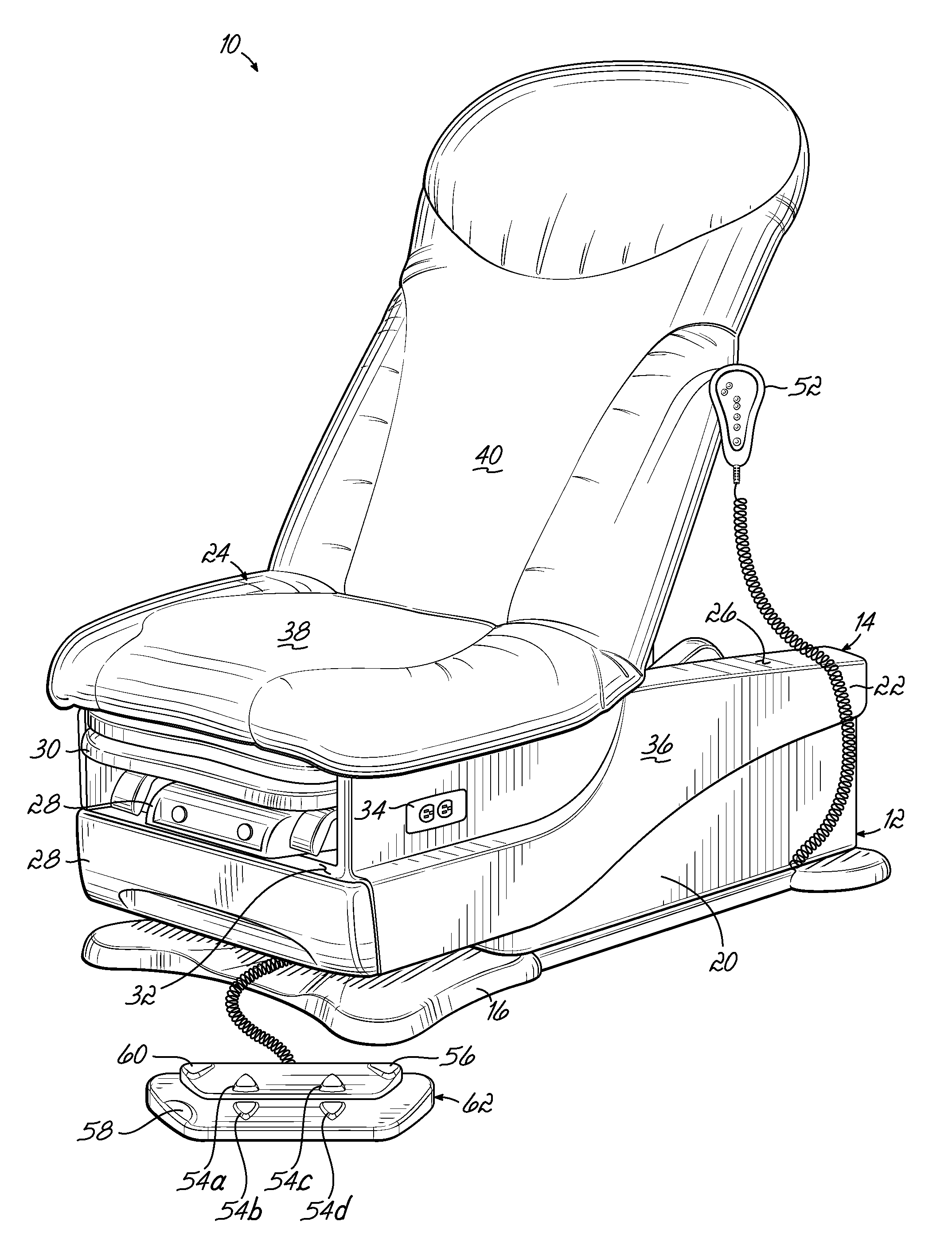
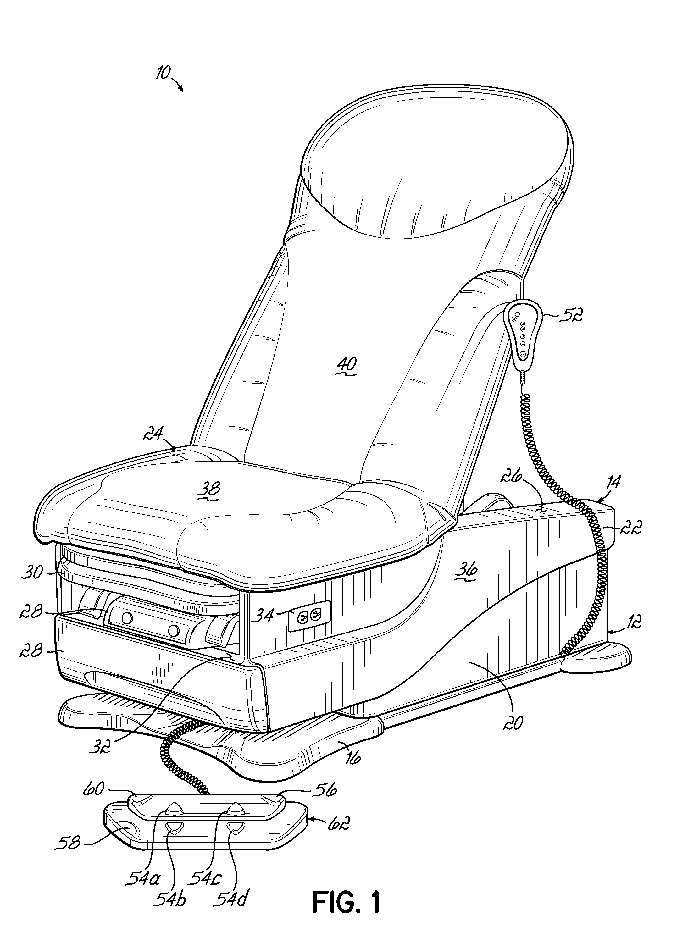
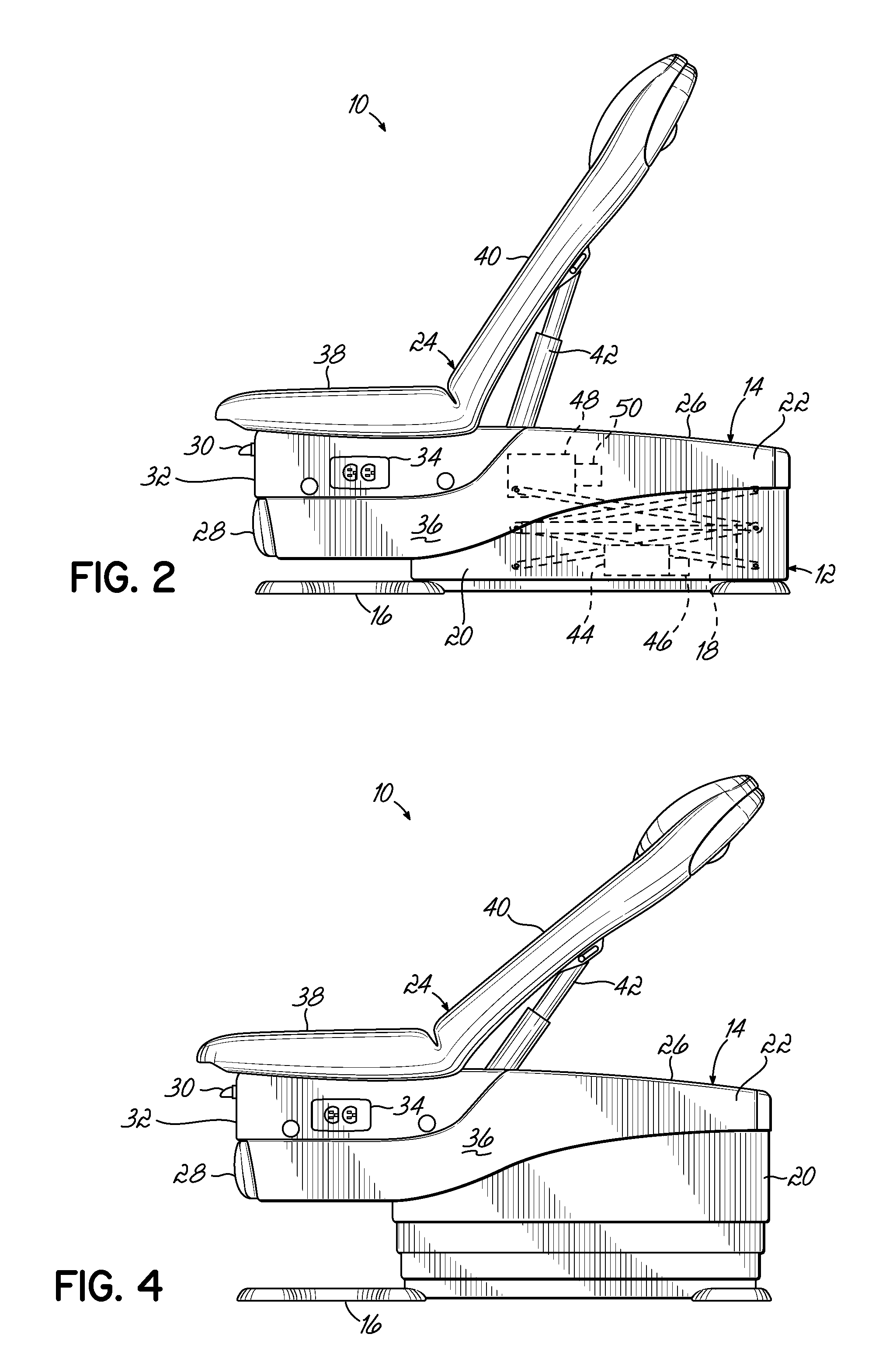
[0031]One embodiment of an examination table 10 is illustrated in FIGS. 1-4. The examination table 10 includes a base portion 12 and a table portion 14 disposed above the base portion 12. The base portion 12 includes a base member 16 for supporting the examination table 10 on a floor surface. The base portion 12 also includes a scissor lift 18 (sho...


PUM


Abstract

A braking action of movement of a support surface on an examination may be accomplished with a motor. The examination table includes a base, a support surface moveable with respect to the base, and a motor having a rotor and a stator. The motor is coupled to the support surface and configured to move the support surface. A motor controller of the examination table is in electrical communication with the motor. The motor controller is configured to brake the movement of the support surface by terminating power to a plurality of windings of the stator of the motor for a predetermined amount of time, and, selectively activating a subset of windings of the plurality of windings of the stator for a predetermined amount of time.

Description

CROSS-REFERENCE TO RELATED APPLICATIONS[0001]This application is a continuation-in-part of U.S. application Ser. No. 12 / 878,321, entitled “BRUSHLESS DC MOTOR STARTS FOR A BARRIER FREE MEDICAL TABLE,” filed on Sep. 9, 2010, the entirety of which is incorporated by reference herein.FIELD OF THE INVENTION[0002]This invention relates generally to examination tables for medical procedures, and more specifically, a motor control for the examination tables.BACKGROUND OF THE INVENTION[0003]Examination tables are incorporated in medical offices for supporting or positioning patients undergoing medical procedures or examinations. Conventional examination tables include a base and a support surface mounted on the base. In order to provide a more comforting support arrangement for the patient, the support surface may include a seat portion and a backrest portion that pivots with respect to the seat portion. Thus, the support surface can be moved from a chair position where the support surface r...

Claims


Application Information

Patent Timeline
Patent Type & Authority Applications(United States)
IPC IPC(8): A61G13/08A61G13/10A61G15/10H02P6/22A61G15/02
CPCA61G13/0018A61G13/06A61G13/08H02P6/24A61G2203/12H02P6/20A61G15/10
Inventor JONES, CHRISHYRE, RODNEY
Owner MIDMARK
Why Eureka
Try Eureka