Stove structure

a technology of stove and structure, which is applied in the direction of stoves or ranges, lighting and heating apparatus, heating types, etc., can solve the problems of high manufacture and maintenance costs, inability to effectively lower the temperature, and lack of heat insulation effect, so as to reduce the contact area of heat conduction, reduce the contact area, and reduce the conductivity

Inactive Publication Date: 2012-03-15
CHANG HSUNYA
View PDF10 Cites 1 Cited by
  • Summary
  • Abstract
  • Description
  • Claims
  • Application Information

AI Technical Summary

Benefits of technology

[0010]The primary object of the present invention is to provide a stove structure which comprises a stove body and a cover. The stove body has a wall portion which has an inner wall and an outer wall. The inner wall and the outer wall are connected by means of a plurality of cross-section conducting members. Between the inner wall, the outer wall and the cross-section conducting members is provided with a low conductivity coefficient member. The stove body includes a heat source portion. The heat source of the heat source portion is charcoal fire, wood wire, gas fire, or electric heat. The cover is disposed on top of the stove body. The cross-section conducting members between the inner wall and the outer wall extend the heat conduction distance and decrease the contact area of heat conduction. The lower conductivity coefficient member and the cross-section conducting members between the inner wall and the outer wall lower the heat conduction rate, so the temperature of the outer wall of the wall portion of the stove body is lowered to the second temperature and the temperature in the heating portion of the stove body is kept at the first high temperature. Through at least one water cooling trough cooperated with a water tray, a ceramic painting and a low conductivity coefficient material layer, the outer wall of the stove body is lowered to the third or fourth temperature so that the outer wall is safe to touch. The present invention provides a high efficiency and a better safety.

Problems solved by technology

This is unable to lower the temperature effectively.
The conventional stove with charcoal or gas as the heat source doesn't have a heat-insulation effect because of a high temperature when in use, which cannot be used indoors.
The manufacture and maintenance costs are high, and it is not environment-friendly.
The dry air from the stove is unable to add humidity to protect the respiratory organs.
This stove cannot be used indoors.
Besides, the first high temperature inside the stove cannot be kept effectively.
The outer wall has a high temperature, which is not safe.

Method used


Image

  • Stove structure
  • Stove structure
  • Stove structure

Examples


Embodiment Construction

[0030]Embodiments of the present invention will now be described, by way of example only, with reference to the accompanying drawings.

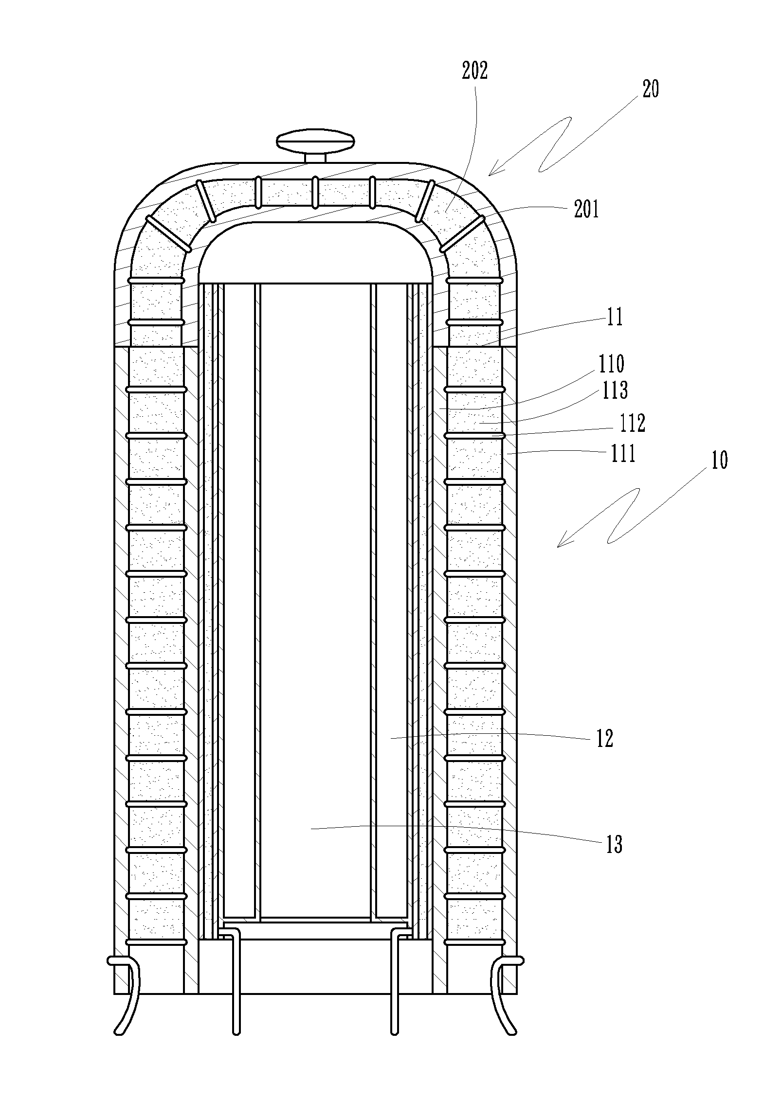
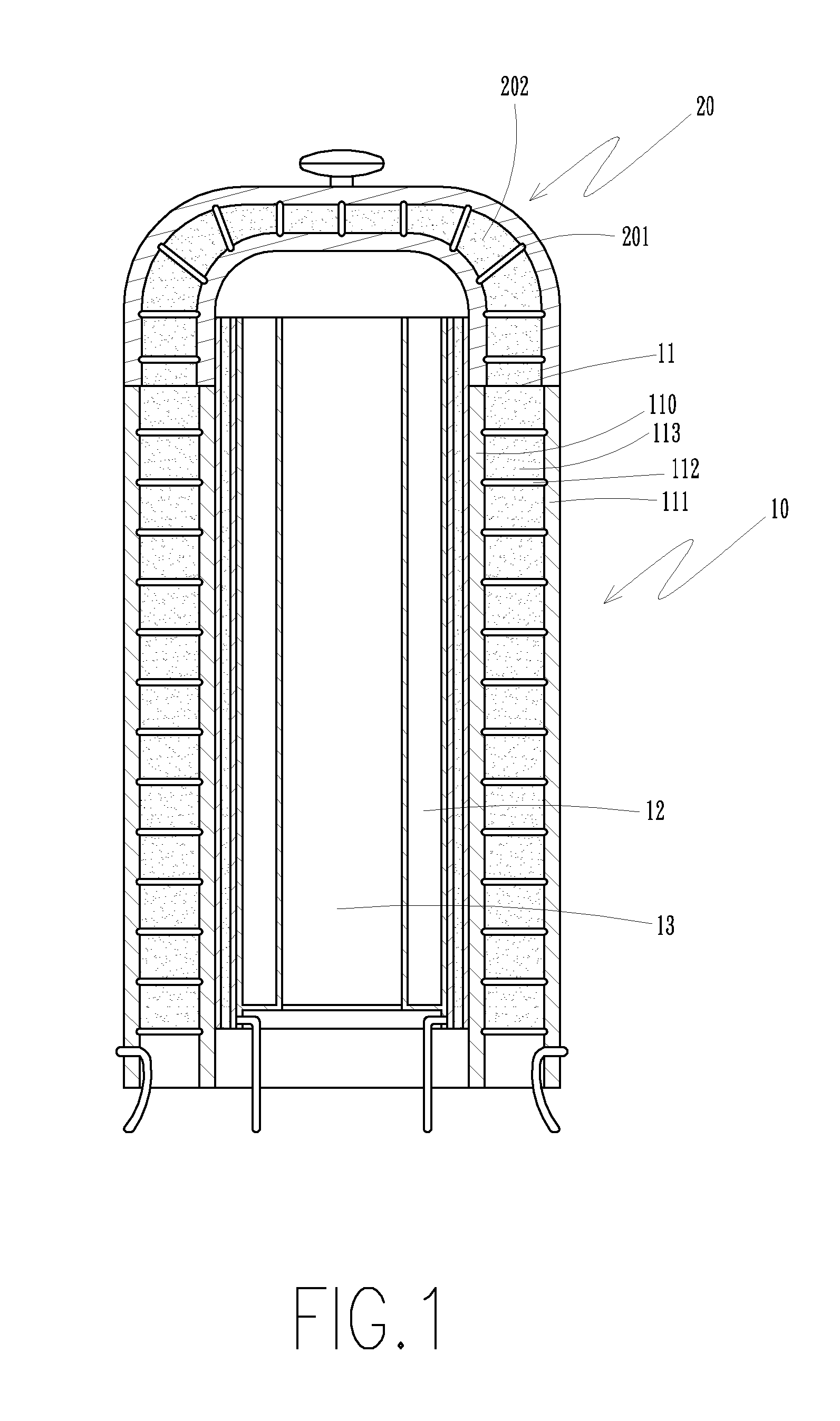
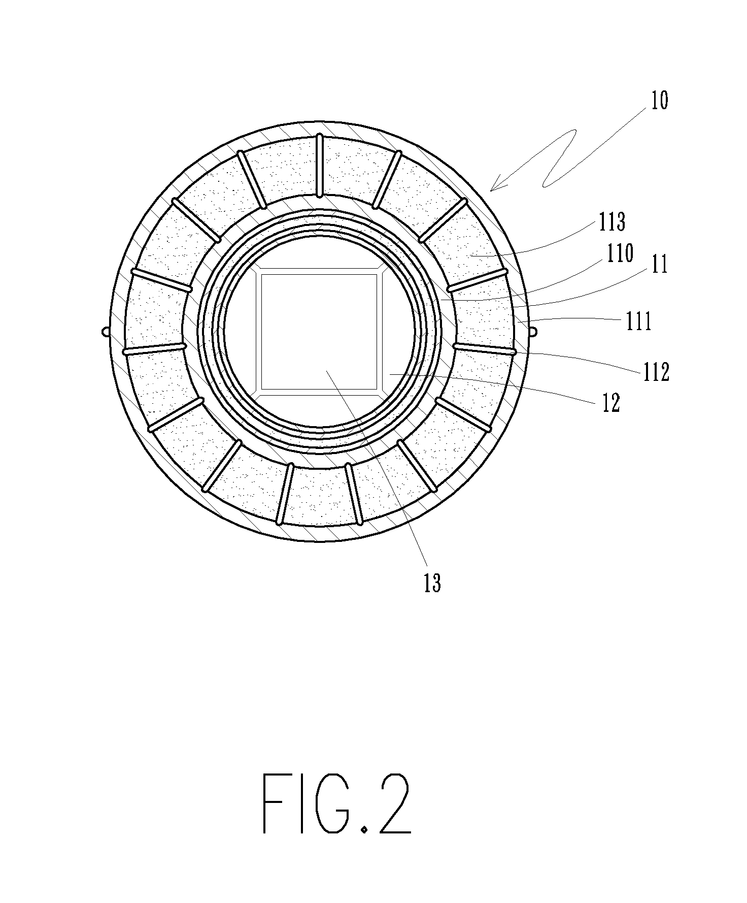
[0031]As shown in FIG. 1 and FIG. 2, the stove structure of the present invention comprises a stove body (10) and a cover (20).

[0032]The stove body (10) has at least one wall portion (11). The stove body (10) comprises a plurality of heat source portions (12) and a heating portion (13). The wall portion (11) has an inner wall (110) and an outer wall (111). The inner wall (110) and the outer wall (111) are connected by means of a plurality of cross-section conducting members (112). The connection is in the way of float-embedding or spot welding. The cross-section conducting members (112) have a U-like shape, wavy shape, spring coil shape or linear shape (not shown in the drawings). Between the inner wall (110), the outer wall (111) and the cross-section conducting members (112) is provided with a low conductivity coefficient member (113). The low condu...


PUM


Abstract

A stove structure includes a stove body. The stove body has a heat source portion and a wall portion. The wall portion has an inner wall and an outer wall. The inner wall and the outer wall are connected by a plurality of cross-section conducting members. Between the inner wall, the outer wall and the cross-section conducting members is provided with a low conductivity coefficient member. The cross-section conducting members extend the heat conduction distance and decrease the contact area of heat conduction. The lower conductivity coefficient member and the cross-section conducting members lower the heat conduction rate. The temperature of the outer wall is lowered to a second temperature and the temperature in the heating portion of the stove body is kept at the first high temperature.

Description

BACKGROUND OF THE INVENTION[0001]1. Field of the Invention[0002]The present invention relates to a stove structure, and more particularly to a stove body which can insulate heat, lower the temperature and keep the high temperate inside the stove body.[0003]2. Description of the Prior Art[0004]A conventional domestic or industrial stove has a wall for keeping warm and heat insulation. The wall comprises a plurality of metallic layers and a thermal material which is switched between the metal layers or disposed on the outer side of the metallic layers to lower the temperature of the outer surface of the metallic layers. As disclosed in Taiwan Patent Nos. M330350, M343690, M356789 and M301629, a vacuum layer or an inert air layer is disposed between the metallic layers. Through the vacuum layer or the inert air layer, the temperature of the outer surface of the metallic layers is lowered. As disclosed in Taiwan Patent No. M360911 and Publication Nos. 381005 and 319684, the metallic lay...

Claims


Application Information

Patent Timeline
Patent Type & Authority Applications(United States)
IPC IPC(8): F24C15/00
CPCF24C15/34
Inventor WANG, PO-TANGYU, HUI-CHUNWANG, KUAN-WENWANG, RIH-YANGWANG, TING-YU
Owner CHANG HSUNYA
Why Eureka
Try Eureka