
Hydraulic Lifting Apparatus

a lifting apparatus and hydraulic technology, applied in the direction of lifting equipment, manufacturing tools, ways, etc., can solve the problems of increasing complexity, increasing complexity, and difficult lifting of manhole covers, so as to facilitate the efficient and safe and convenient removal and replacement

Inactive Publication Date: 2012-03-15
E NORTON & ASSOCS
View PDF19 Cites 10 Cited by
  • Summary
  • Abstract
  • Description
  • Claims
  • Application Information

AI Technical Summary

Benefits of technology

The invention is a hydraulic lifting apparatus that makes it safe and easy to remove and replace rectangular manhole covers. It allows personnel to safely perform this task from a distance, using a crane or other rigging equipment. The apparatus has a lifting member connected to a hydraulic actuation device and multiple lifting hooks. The hydraulic actuation device is activated by personnel from a safe distance, and the lifting hooks securely interface with lifting blocks on the manhole cover. The apparatus and manhole cover can then be lifted by the rigging structure. When the manhole cover is replaced, the hydraulic actuation device is de-activated to release the lifting hooks from the manhole cover. Overall, this invention provides a convenient and safe way to manage manhole covers.

Problems solved by technology

Underground utility installations (such as sewer pipes, electrical cable conduits, and the like) have become increasingly complex.
This increasing complexity often requires frequent access by construction or maintenance personnel in order to install new utilities or upgrade and maintain existing utilities.
As a result, the manhole covers can be very heavy and difficult to lift, and may pose a safety risk to personnel who attempt to remove a manhole cover for entry into an access conduit.
Existing equipment and techniques, however, still require that considerable effort be expended by personnel to remove the manhole cover and that personnel remain in close proximity to the access conduit when the manhole cover is being removed.
Under some circumstances, conditions may arise that make manhole cover removal very dangerous.
Removal of the manhole cover may cause ignition of the gas, resulting in an explosion.
Any personnel who are in close proximity to the access conduit therefore face severe danger and the possibility of extreme injury.

Method used


Image

  • Hydraulic Lifting Apparatus
  • Hydraulic Lifting Apparatus
  • Hydraulic Lifting Apparatus

Examples


Embodiment Construction

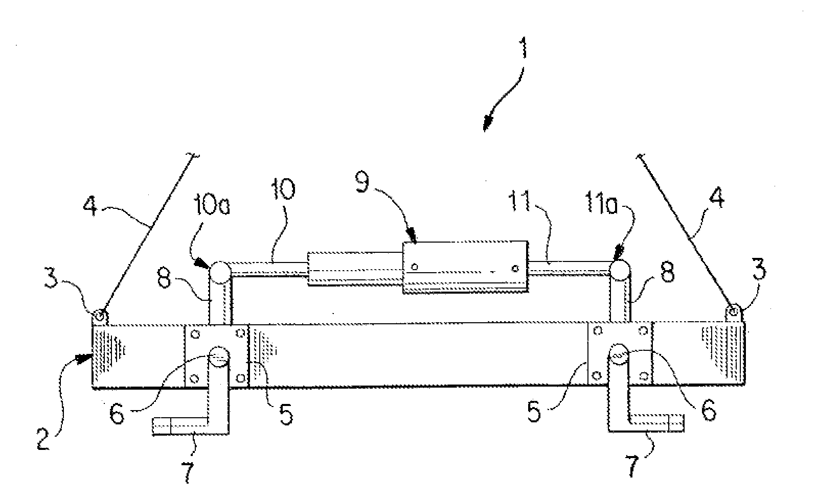
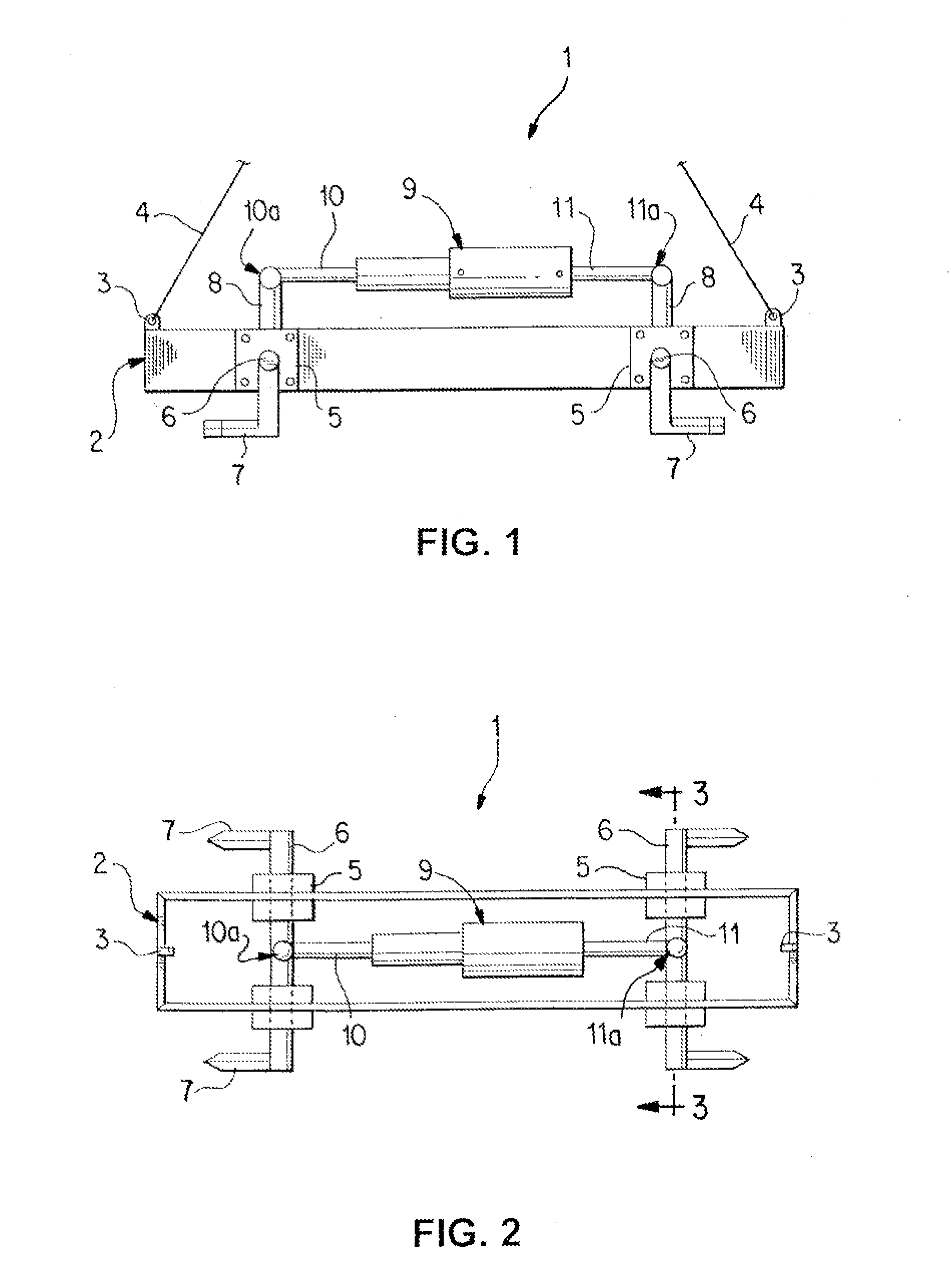
[0013]A hydraulic lifting apparatus 1 in accordance with one embodiment of the invention is shown in FIGS. 1 and 2. Hydraulic lifting apparatus 1 includes a lifting member 2. Lifting member 2 may be of any suitable construction. In the embodiment of the hydraulic lifting apparatus 1 shown in FIGS. 1 and 2, the lifting member 2 has an elongated box-type structure, constructed of four steel plates fastened together in a suitable fashion, for example, by welding. Alternatively, lifting member 2 could be constructed of a frame that includes tubular members. Lifting member 2 preferably includes a plurality of lifting points 3 to which an appropriate rigging structure may be affixed in order to lift the complete hydraulic lifting apparatus 1 with rigging or lifting equipment, such as, a crane. For example, rigging lines 4 may be attached to lifting points 3. Rigging lines 4 may be constructed of steel wire, chain, or any other suitable material known in the art.

[0014]Fastened to the lifti...


PUM

PropertyMeasurementUnit
shapesaaaaaaaaaa
sizesaaaaaaaaaa
durabilityaaaaaaaaaa

Abstract

The invention provides a hydraulic lifting apparatus that permits convenient and efficient removal and replacement of a rectangular manhole cover from an access conduit. The invention further allows personnel to perform such removal and replacement from a safe distance. In one embodiment, the hydraulic lifting apparatus comprises a lifting member coupled to a hydraulic actuation device that is movably connected to lifting hooks to permit interface with and release from the lifting blocks of the rectangular manhole cover.

Description

FIELD OF THE INVENTION[0001]The invention relates in general to a hydraulic lifting apparatus and, more particularly, to a hydraulic lifting apparatus used to lift rectangular manhole covers, street gratings, and the like.BACKGROUND[0002]Underground utility installations (such as sewer pipes, electrical cable conduits, and the like) have become increasingly complex. This increasing complexity often requires frequent access by construction or maintenance personnel in order to install new utilities or upgrade and maintain existing utilities. Since these utility installations are located underground, access to them is generally accomplished through an entrance hole set at ground level. Personnel typically descend through the entrance hole into a vertical access conduit that permits access to the utility installations. These access conduits are commonly referred to as “manholes”.[0003]The entrance hole of the access conduit is usually closed with some type of cover, such as a manhole co...

Claims


Application Information

Patent Timeline
Patent Type & Authority Applications(United States)
IPC IPC(8): B66F11/00B23P17/00
CPCB66C1/28B66F19/005Y10T29/49815E02D29/1445E01C19/52
Inventor PANIO, MICHAEL T.
Owner E NORTON & ASSOCS
Learn More