
Air spring for a heavy-duty vehicle with damping features

a technology of air springs and heavy-duty vehicles, which is applied in the direction of shock absorbers, mechanical equipment, transportation and packaging, etc., can solve the problems of adding complexity and weight adding additional maintenance and/or replacement costs to the axle/suspension system, and reducing the amount of cargo that can be carried by the heavy-duty vehicle. , to achieve the effect of reducing complexity, reducing weight and cost, and reducing the size of the shock absorb

Active Publication Date: 2012-03-15
HENDRICKSON USA L L C
View PDF17 Cites 44 Cited by
  • Summary
  • Abstract
  • Description
  • Claims
  • Application Information

AI Technical Summary

Benefits of technology

[0015]A further objective of the present invention is to eliminate or reduce the size of the shock absorber, thereby reducing complexity, saving weight and cost, and allowing the heavy-duty vehicle to haul more cargo.
[0016]Yet another objective of the present invention is to provide an air spring having optimized damping characteristics that is relatively simple and which eliminates or reduces costly repairs and / or maintenance costs.

Problems solved by technology

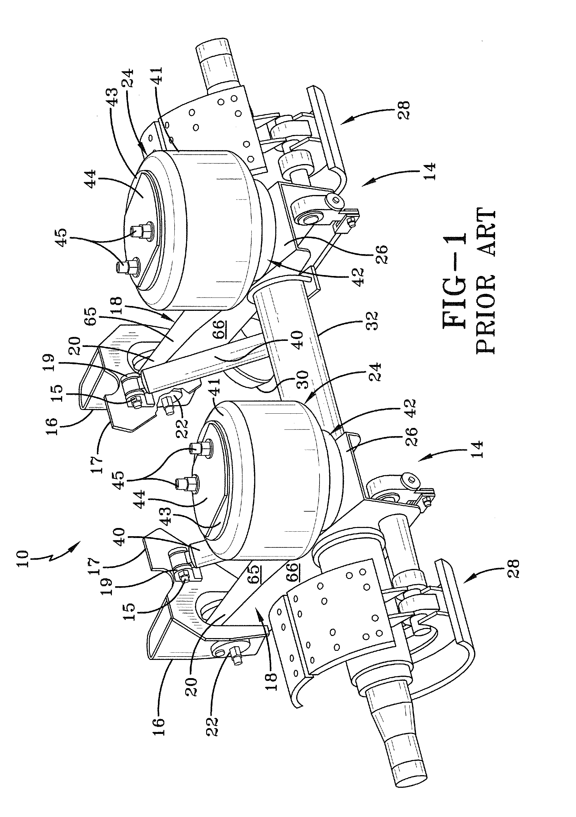
These shock absorbers add complexity and weight to the axle / suspension system.
Moreover, because the shock absorbers are a service item of the axle / suspension system that will require maintenance and / or replacement from time to time, they also add additional maintenance and / or replacement costs to the axle / suspension system.
Because shock absorbers are relatively heavy, these components add undesirable weight to the axle / suspension system and therefore reduce the amount of cargo that can be carried by the heavy-duty vehicle.
Depending on the shock absorbers employed, they also add varying degrees of complexity to the axle / suspension system which is also undesirable.
However, the prior art air springs that include valves are complicated and require valve components that can break down over time requiring expense and time to replace.
Moreover, these rubber flaps, like the valves, are additional components within the air spring that can wear, requiring costly repairs and / or maintenance.
In addition, these prior art air springs, which include openings between the bellows and the piston, do not consider the volume of the bellows chamber, the volume of the piston chamber or the size and / or number of openings formed between and communicating with the bellows chamber and the piston chamber in order to provide improved damping characteristics to the air spring.

Method used


Image

  • Air spring for a heavy-duty vehicle with damping features
  • Air spring for a heavy-duty vehicle with damping features
  • Air spring for a heavy-duty vehicle with damping features

Examples


first embodiment

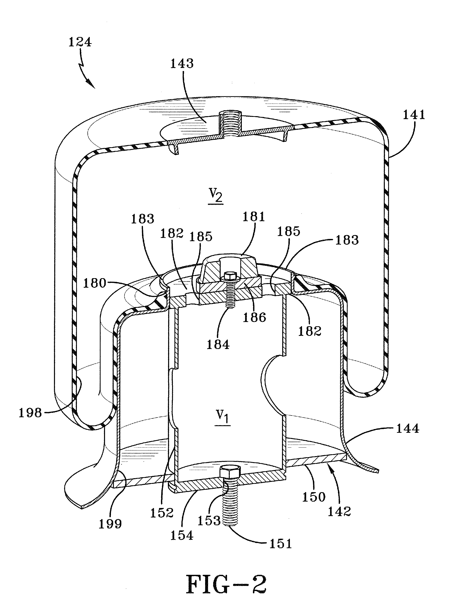
[0037]Having now described the structure of first embodiment air spring 124 of the present invention, the operation of the damping characteristics of the air spring will be described in detail below. When axle 32 of axle / suspension system 10 experiences a jounce event, such as when the vehicle wheels encounter a curb or a raised bump in the road, the axle moves vertically upwardly toward the vehicle chassis. In such a jounce event, bellows chamber 198 is compressed by axle / suspension system 10 as the wheels of the vehicle travel over the curb or the raised bump in the road. The compression of air spring bellows chamber 198 causes the internal pressure of the bellows chamber to increase. Therefore, a pressure differential is created between bellows chamber 198 and piston chamber 199. This pressure differential causes air to flow from bellows chamber 198, through piston top plate openings 185 and into piston chamber 199. The restricted flow of air between bellows chamber 198 into pist...

second embodiment

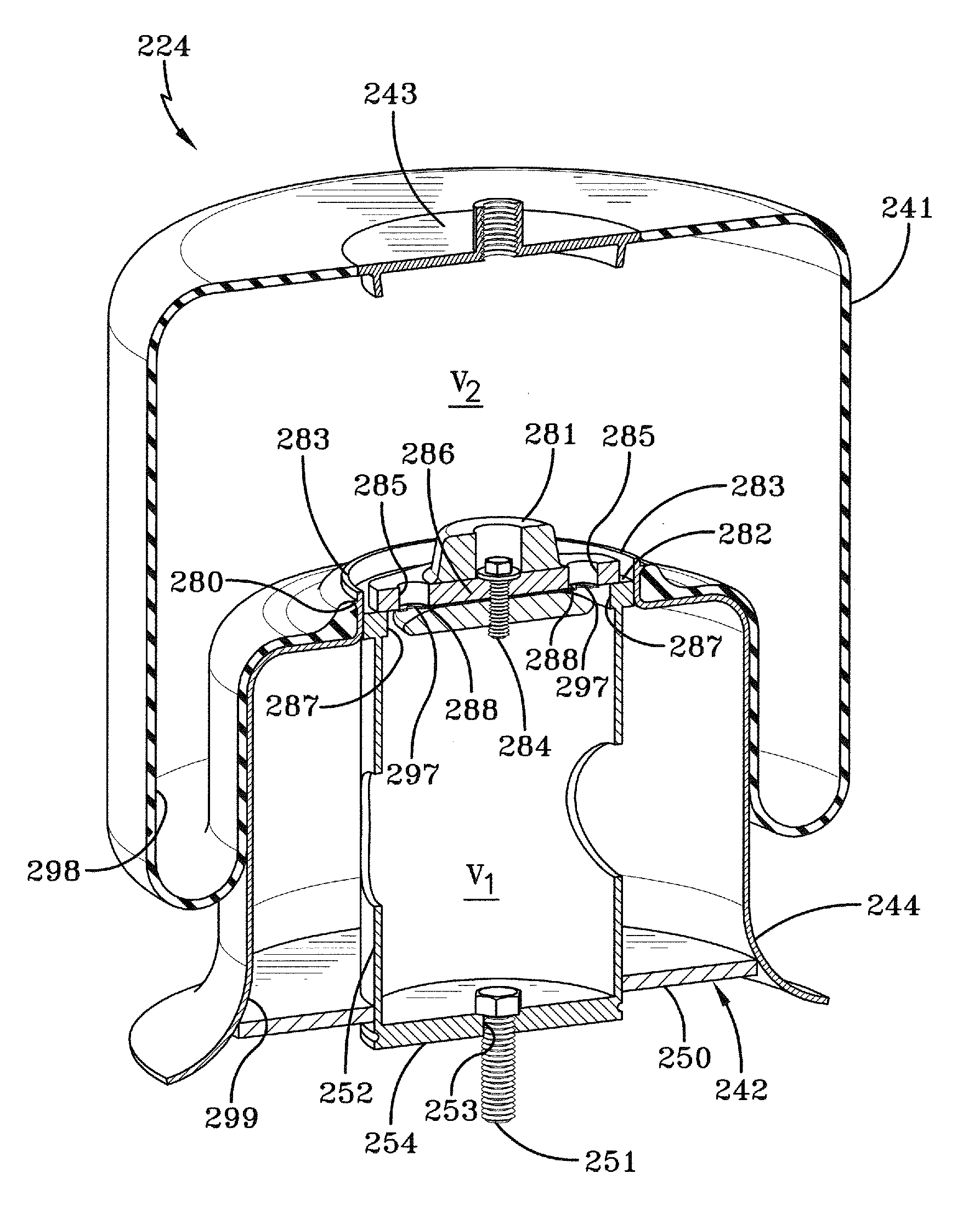
[0046]Having now described the structure of second embodiment air spring 224 of the present invention, the operation of the air spring will be described in detail below. When axle 32 of axle / suspension system 10 experiences a jounce event, such as when the vehicle wheels encounter a curb or a raised bump in the road, the axle moves vertically upwardly toward the vehicle chassis. In such a jounce event, bellows chamber 298 is compressed by axle / suspension system 10 as the wheels of the vehicle travel over the curb or the raised bump in the road. The compression of air spring bellows chamber 298 causes the internal pressure of the bellows chamber to increase. Therefore, a pressure differential is created between bellows chamber 298 and piston chamber 299. This pressure differential causes air to flow from bellows chamber 298, through bumper mounting plate openings 285, causing flappers 288 to be forced downwardly as described in detail above and shown in FIG. 5, allowing air to flow i...


PUM


Abstract

An air spring for a heavy-duty vehicle axle / suspension system includes a bellows chamber operatively connected to a piston chamber. An opening is disposed between the bellows chamber and the piston chamber in order to allow fluid to communicate between the bellows chamber and the piston chamber. The cross-sectional area of the opening and the volumes of the bellows chamber and the piston chamber are tuned in order to optimize the damping characteristics of the air spring.

Description

CROSS-REFERENCE TO RELATED APPLICATION[0001]This application claims the benefit of U.S. Provisional Patent Application Ser. No. 61 / 381,477, filed Sep. 10, 2010.BACKGROUND OF THE INVENTION[0002]1. Field of the Invention[0003]The invention relates generally to the art of axle / suspension systems for heavy-duty vehicles. More particularly, the invention relates to air-ride axle / suspension systems for heavy-duty vehicles which utilize an air spring to cushion the ride of the vehicle. More specifically, the invention is directed to an air spring of a heavy-duty vehicle air-ride axle / suspension system, in which the air spring is optimized to provide damping characteristics to the air spring and in turn to the axle / suspension system based upon the volume of the bellows chamber of the air spring, the volume of the piston chamber of the air spring, and the size(s) of one or more openings formed in the air spring between and communicating with the bellows chamber and the piston chamber. Even m...

Claims


Application Information

Patent Timeline
IPC IPC(8): B60G15/14F16F9/05
CPCB60G11/27B60G2202/152B60G13/10F16F9/05B60G2206/424
Inventor WESTNEDGE, ANDREW J.KEELER, MICHAEL J.
Owner HENDRICKSON USA L L C
Learn More