
Composite transformer

a transformer and composite technology, applied in the direction of transformer/inductance details, transformer/inductance magnetic core, electrical apparatus, etc., can solve problems such as loss of magnetic energy, and achieve the effect of reducing magnetic energy loss

Active Publication Date: 2012-03-15
HONDA MOTOR CO LTD
View PDF14 Cites 8 Cited by
  • Summary
  • Abstract
  • Description
  • Claims
  • Application Information

AI Technical Summary

Benefits of technology

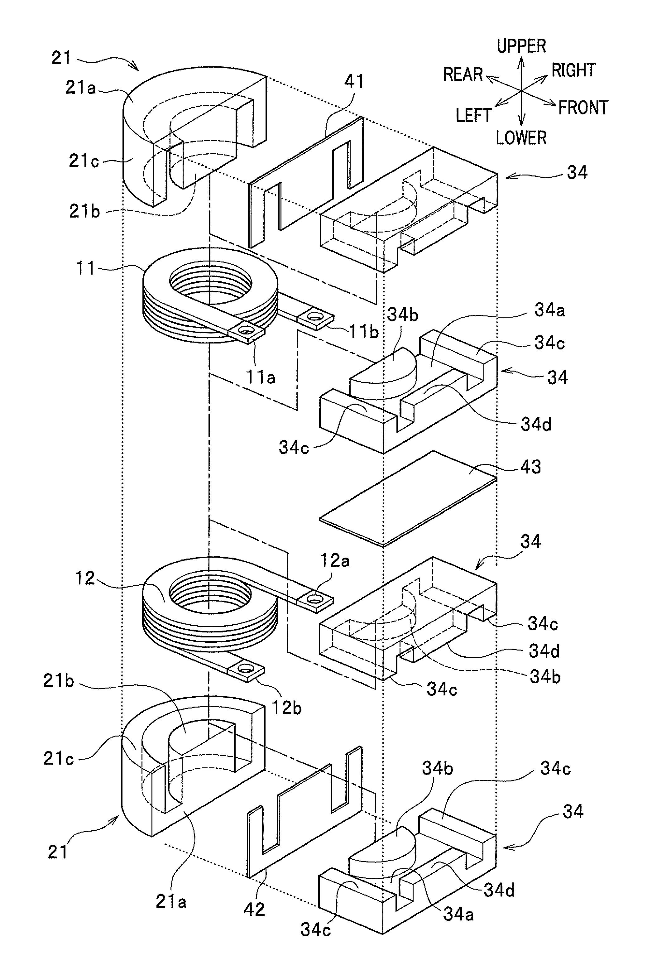
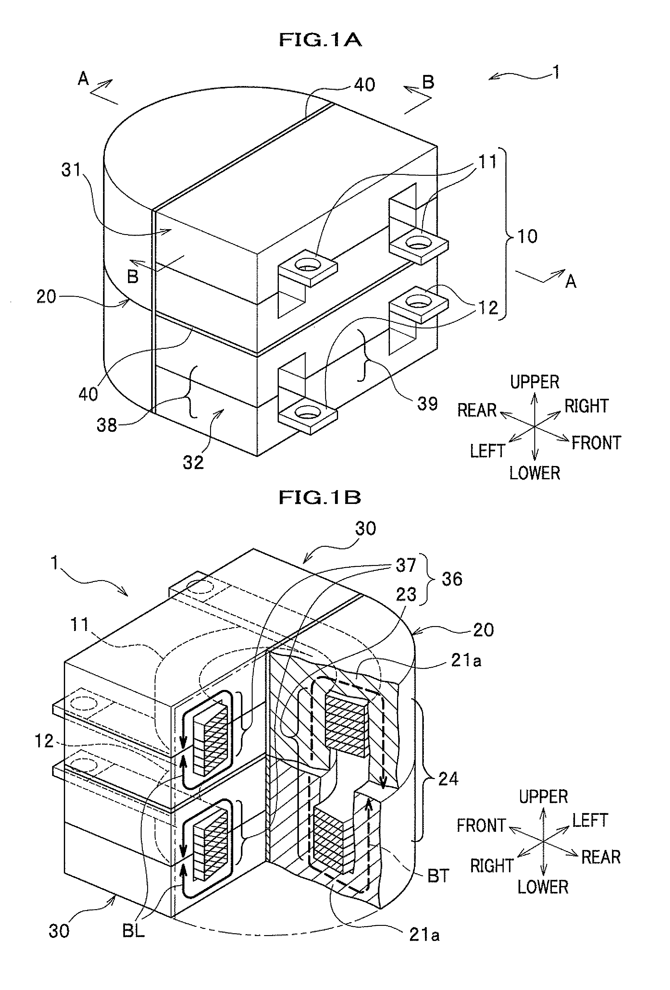
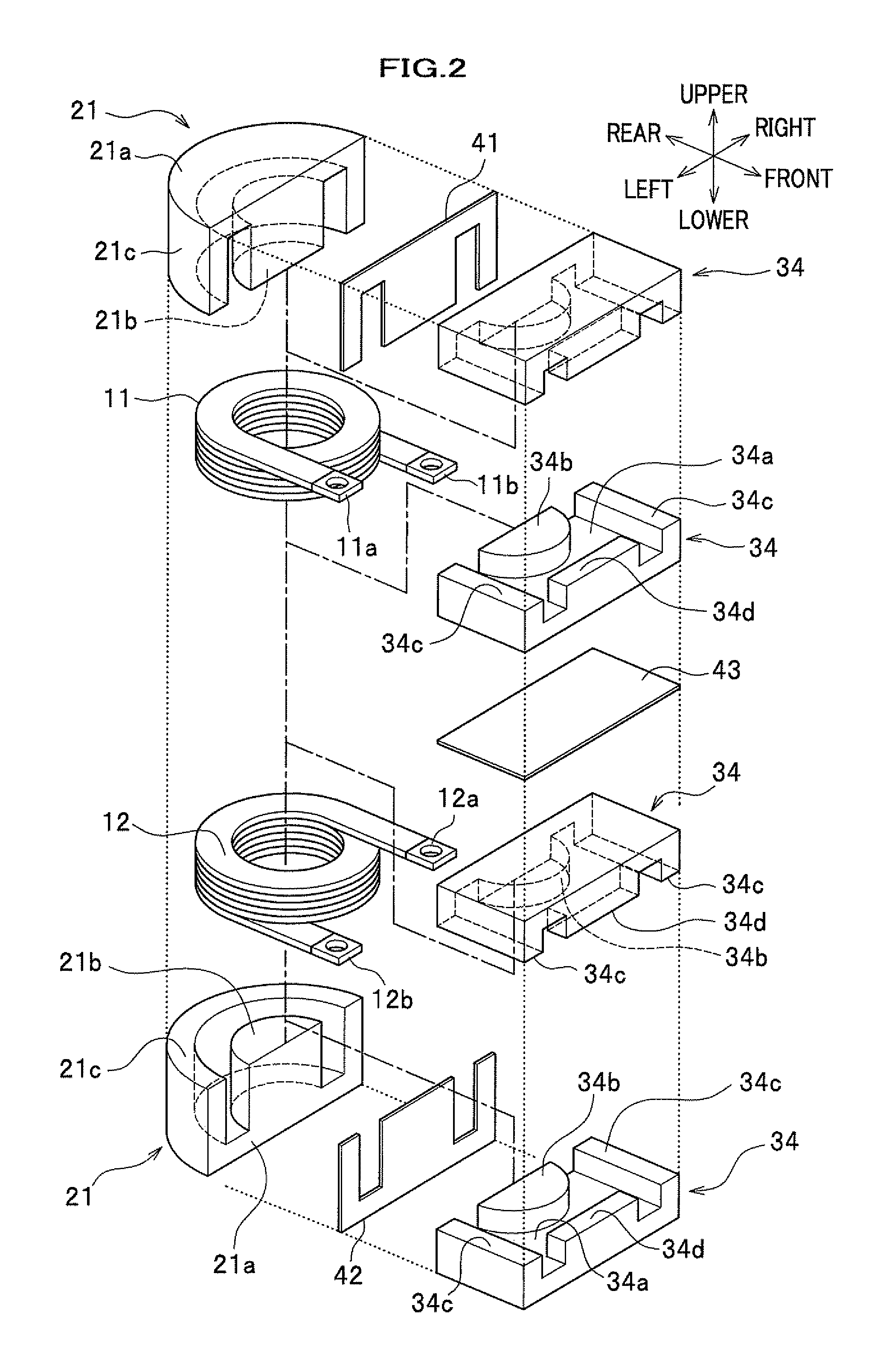
The present invention provides a combined type of transformer that includes two windings and a transformer core with a transformer magnetic leg portion and an inductor magnetic leg portion. The windings are wound in a way that the magnetic fluxes generated by them cancel out each other, providing magnetic induction to boost the output voltage of the other winding. The transformer core includes a transformer magnetic leg portion and an inductor magnetic leg portion, and the windings are wound to reduce energy loss caused by excessive magnetic flux density. The combined type of transformer also has improved efficiency in connecting with an external electric circuit and reduced loss of magnetic energy due to residual magnetization. Additionally, a magnetic insulation sheet may be added to prevent magnetic fields from influencing on each other. The composite transformer of the present invention is down-sized with reduction in magnetic energy loss.

Problems solved by technology

Therefore, this configuration may invite an excessively high magnetic density over a saturation magnetic flux density at the center magnetic leg portion which causes a loss in magnetic energy.

Method used


Image

  • Composite transformer
  • Composite transformer
  • Composite transformer

Examples


example

[0147]Hereinafter, will be described examples according to the embodiment of the present invention.

[0148]In this example, the composite transformer 1 is installed in a DC-DC converter and a boosting operation is performed by turning on and off the switching elements.

[0149]In addition, the number of turns of the windings installed in the composite transformer is changed and a volume of the composite transformer having the number of turns of windings is calculated.

[0150]In addition, every time composite transformer of which the number of turns of the winding is changed, a copper loss and an iron loss (W), which are losses in the magnetic part, are calculated. In addition, the calculation condition of the applied voltages, etc. are given in Table 1.

TABLE 1Frequency ofAppliedInputOutputswitchingRipplevoltage(Vin)current (Iin)power (Pout)element (Tsw)current(Vin)70 V150 A10.5 Kw45 KHz17 Ap-p

[0151]In the composite transformer of the example, ferrite is used as a material of the transforme...


PUM

PropertyMeasurementUnit
magnetic fluxaaaaaaaaaa
magnetic fluxesaaaaaaaaaa
polarityaaaaaaaaaa

Abstract

A composite (combined type of) transformer includes: a transformer core including a plurality of transformer magnetic leg portions, a transformer magnetic leg portion, and a pair of transformer bases; a plurality of inductor cores each including an inductor magnetic leg portions, inductor outer magnetic leg portions, and a pair of inductor bases; and a plurality of windings wound around the transformer magnetic leg portion and the inductor magnetic leg portions. The windings are wound to generate magnetic fluxes in such directions as to be cancelled out in a magnetic closed circuit in the transformer core.

Description

CROSS REFERENCE TO RELATED APPLICATION[0001]This application claims the foreign priority benefit under Title 35, United States Code, §119(a)-(d) of Japanese Patent Application No. 2010-197416, filed on Sep. 3, 2010 in the Japan Patent Office, the disclosure of which is herein incorporated by reference in its entirety.BACKGROUND OF THE INVENTION[0002]1. Field of the Invention[0003]The present invention relates to a composite transformer (combined type of transformer) and particularly to a composite transformer with a little energy loss used in a power converter for down sizing.[0004]2. Description of the Related Art[0005]Composite transformers (combined type of transformers) are known which are used in a DC (Direct Current)-DC converter. JP 2005-224058 discloses a DC-DC converter having a magnetic flux canceling type of transfer (hereinafter referred to only as a transformer) in which a plurality of windings are disposed in such a direction that the magnetic fluxes generated by respe...

Claims


Application Information

Patent Timeline
Patent Type & Authority Applications(United States)
IPC IPC(8): H01F27/24
CPCH01F30/10H01F27/263
Inventor NAGANO, MASAOHASHINO, SATOSHIHIRAKAWA, MITSUAKI
Owner HONDA MOTOR CO LTD
Learn More