
Zero-Voltage-Switching Scheme for High-Frequency Converter

a converter and zero-voltage technology, applied in the direction of electric variable regulation, process and machine control, instruments, etc., can solve the problems of complex operation logic, loss of reverse recovery, and limit efficient operation at much higher frequency of inverter operation

Active Publication Date: 2012-03-15
THE BOARD OF TRUSTEES OF THE UNIV OF ILLINOIS
View PDF7 Cites 54 Cited by
  • Summary
  • Abstract
  • Description
  • Claims
  • Application Information

AI Technical Summary

Benefits of technology

"The present invention provides a method for operating an ac / ac converter circuit for a high-frequency-link converter. This method can be used for either a cycloconverter-type or a rectifier-type converter, and can be either half-bridge or full-bridge, and single phase or multiple phases. The method involves a process where the converter circuit converts an AC input voltage to an AC output voltage. When the AC input voltage is zero, the method involves causing both switches in each arm of the converter circuit to be on, allowing current to flow through each arm in opposite directions. When the AC input voltage reaches the positive or negative DC level, the method involves reversing the current direction through one of the arms. The method also involves discharging the output capacitance of the selected switch in the other arm and then turning it on again when the AC input voltage reaches zero. The technical effect of this method is to improve the efficiency and reliability of high-frequency-link converters."

Problems solved by technology

However, operation of such a scheme involves rectifier diodes, which experience reverse recovery losses if the inverter operates at high switching frequencies.
This leads to complex operational logic.
Further, the differences in the switching actions makes it apparent that additional switching for the non-unity-power-factor case leads to additional switching losses for the ac / ac converter, which can limit efficient operation at much higher frequencies of inverter operation.

Method used


Image

  • Zero-Voltage-Switching Scheme for High-Frequency Converter
  • Zero-Voltage-Switching Scheme for High-Frequency Converter
  • Zero-Voltage-Switching Scheme for High-Frequency Converter

Examples


Embodiment Construction

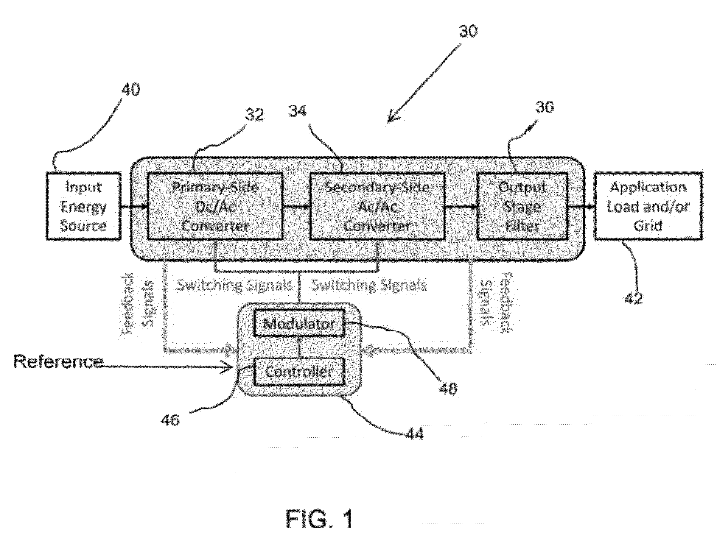
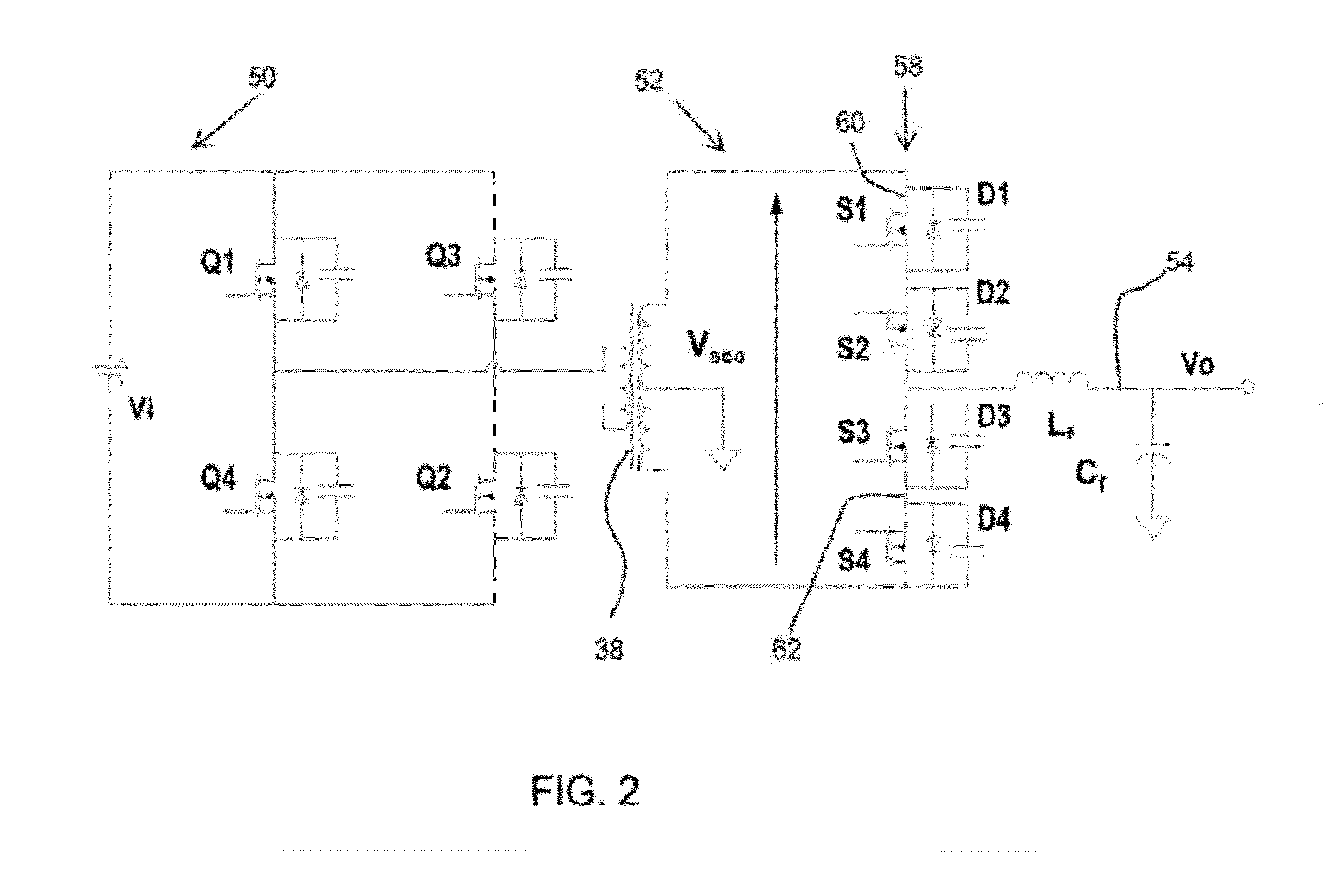
[0027]Example embodiments of the present invention provide, among other things, a zero-voltage-switching (ZVS) scheme for an ac / ac converter that mitigates enhanced ac / ac-converter losses at frequencies much higher than 20 kHz. During turn-on and turn-off of switches, if the product of switch current and switch voltage is zero, then the switch is said to undergo a “soft switching,” or else it is “hard switching.” If the current approaches zero before the voltage, the soft switching mechanism is called zero-current switching (ZCS). If the voltage goes to zero before the current, the soft switching mechanism is called zero-voltage switching (ZVS).

[0028]Methods are provided according to example embodiments of the present invention for a high-frequency link converter having a high-frequency link transformer coupled to a primary side converter and a secondary side converter. The secondary side converter comprises an ac / ac converter circuit for converting an ac input voltage, varying betw...


PUM


Abstract

Method for operating an ac / ac converter circuit for a high-frequency-link converter. The ac / ac converter circuit converts an ac input voltage to an ac output voltage. When the ac input voltage is zero, each of a pair of switches for both first and second arms are caused to be on. Current flows through the first arm along a first direction and through the second arm along a second, opposite direction. Next, when the ac input voltage is zero, a selected switch in the second arm is caused to be turned off. The position of the switches can be maintained as the ac input voltage transitions to a dc level, reaches the dc level, approaches zero, and again reaches zero. When the ac input voltage again reaches zero, the selected switch for the second arm is caused to be turned on.

Description

PRIORITY CLAIM AND REFERENCE TO RELATED APPLICATION[0001]This application claims the benefit of U.S. Provisional Application Ser. No. 61 / 297,425, filed Jan. 22, 2010, under 35 U.S.C. §119.STATEMENT OF GOVERNMENT INTEREST[0002]This invention was made with government support under National Science Foundation Grant No. 0725887. The government has certain rights in the invention.FIELD OF THE INVENTION[0003]A field of the invention is power converters.BACKGROUND OF THE INVENTION[0004]The need for energy security and energy surety is slowly driving worldwide end-energy users towards renewable and alternative sources of energy. The impact of this movement appears to have a correlation with progressively reduced cost of the energy sources. A further need is to reduce the cost of the interfacing power-electronics system (PES), which is relatively difficult since power electronics is already a relatively mature field.[0005]As a nonlimiting example, high efficiency, low cost, and high power de...

Claims


Application Information

Patent Timeline
Patent Type & Authority Applications(United States)
IPC IPC(8): H02M7/5387
CPCY02B70/1491H02M2001/0058H02M7/4807H02M1/0058Y02B70/10
Inventor MAZUMDER, SUDIP K.
Owner THE BOARD OF TRUSTEES OF THE UNIV OF ILLINOIS
Learn More