Self-oscillation type resonant flyback converter utilizing charge stored effect of the P-N diode

a self-oscillation type, flyback converter technology, applied in the direction of dc-dc conversion, power conversion systems, climate sustainability, etc., can solve the problems of large switching loss and inability to maintain integrity, and achieve high reliability

Inactive Publication Date: 2002-06-11
INTEGRATED PROGRAMMABLE COMM
View PDF5 Cites 47 Cited by
  • Summary
  • Abstract
  • Description
  • Claims
  • Application Information

AI Technical Summary

Benefits of technology

In view of the foregoing, it is an object of the present invention to provide a self-oscillation type resonant flyback converter that overcomes the above-described drawbacks of prior art without modifying topology. It is a further object of the present invention to provide a self-oscillation type resonant flyback converter that facilitates soft switching, at arbitrary frequencies, has an improved efficiency and could offer a larger power than conventional flybak converter.
In order to boost the performance of resonant converter which accepts a broad range of input voltage and guarantees switching at zero voltage of the switching transistor. By proper selection of the reverse recovery time of the power diode, producing reverse recovery current of the power diode through the secondary winding and the output capacitor before a free resonance period starts, adding to energy of resonant circuit, forming effective to discharge an electric charge of said snubber capacitor.

Problems solved by technology

Because of discharge of the snubber capacitor Cs, causing a current spike, the product of the collector current and the voltage between the collector and emitter causes a large switching loss at the time when the switching transistor Q1 is turned on, especially in case of high output voltage and under high power conditions.
The design of a conventional flyback converter (square wave systems) is valid, but not in its integrity.

Method used


Image

  • Self-oscillation type resonant flyback converter utilizing charge stored effect of the P-N diode
  • Self-oscillation type resonant flyback converter utilizing charge stored effect of the P-N diode
  • Self-oscillation type resonant flyback converter utilizing charge stored effect of the P-N diode

Examples


Embodiment Construction

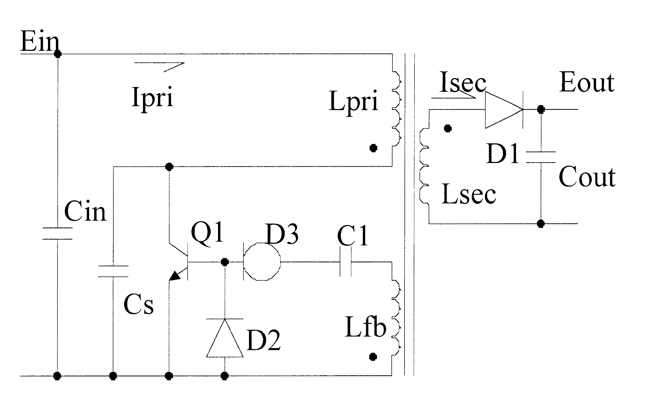
In FIG. 1 there is shown a preferred embodiment of a self-oscillation type resonant flyback converter comprising a transformer with a primary winding inductance Lpri, a secondary winding inductance Lsec and a feedback winding inductance Lfb. A primary-side switching transistor Q1 is connected in series with the primary winding Lpri across an input dc voltage Ein and an input filter capacitor Cin, a snubber capacitor Cs is connected in parallel with switching transistor Q1. A secondary-side power diode D1 is connected in series with the secondary winding Lsec across an output dc voltage Eout and an output filter capacitor Cout.

In parallel with the feedback winding there is a delay driving circuit formed by a delay diode D2, a constant-current diode D3 and a capacitor C1, wherein said delay diode D2 is connected in parallel with the base and emitter of the switching transistor Q1 in FIG. 1. The primary-side current is designated as Ipri, and the secondary-side current is designated as...


PUM


Abstract

A self-oscillation type resonant flyback converter includes a series combination of a primary winding and a switching transistor. A secondary winding is connected to a power diode and to an output capacitor. A feedback winding is connected to a delay driving circuit comprising a delay diode, a constant-current diode and a capacitor. The delay driving circuit is provided to delay a positive feedback signal from said feedback winding, so that when said power diode becomes non-conducting, said delay diode becomes in the reverse conduction state, starting a free resonance period that concludes when the said delay diode becomes non-conducting and the switching transistor is achieved at zero voltage switching.

Description

OBJECT OF THE INVENTIONThe present invention relates to a self-oscillation type resonant flyback converter utilizing charge stored effect of the P-N diode. The switching action of the switching transistor is done at zero voltage through the selections of a reverse recovery time of said delay diode and power diode, respectively. Due to the simplicity of the circuit, i.e., very few components, and its high reliability, it can be implemented using high-density packaging techniques. Such a resonant converter is useful in high-voltage, high-power dc-to-dc converters for distributed power supply systems.A ringing choke converter has been often utilized as a self-oscillation type power supply. Referring to FIG. 3, a conventional ringing choke converter comprises a transformer with a primary winding inductance Lpri, a secondary winding inductance Lsec and a feedback winding inductance Lfb. A primary-side switching transistor Q1 is connected in series with the primary winding Lpri across an ...

Claims


Application Information

Patent Timeline
Patent Type & Authority Patents(United States)
IPC IPC(8): H02M3/24H02M3/338
CPCH02M3/338Y02B70/1433Y02B70/10
Inventor WANG, JOHNSON
Owner INTEGRATED PROGRAMMABLE COMM
Why Eureka
Try Eureka