Method For Determining The Registration Of A Structure On A Photomask And Apparatus To Perform The Method

a technology of structure registration and photomask, which is applied in the field of method for determining the registration of structures on photomasks, can solve the problems of considerable distortion, inability to achieve the requirements imposed, and inability to use cross-correlation for position determination

Active Publication Date: 2012-03-15
CARL ZEISS SMT GMBH +1
View PDF11 Cites 28 Cited by
  • Summary
  • Abstract
  • Description
  • Claims
  • Application Information

AI Technical Summary

Benefits of technology

[0064]This measure has the advantage of making it possible also to determine the positions of regions that have intensity discontinuities in their edge regions.
[0065]These discontinuities make it impossible to use cross-correlation for position determinat

Problems solved by technology

These methods have not yet made it possible to achieve the requirements imposed on the next generation of position measuring devices.
Proximity effects may cause considerable distortion, especially when measurements are being performed on small patterns close to the limit of resolution o

Method used


Image

  • Method For Determining The Registration Of A Structure On A Photomask And Apparatus To Perform The Method
  • Method For Determining The Registration Of A Structure On A Photomask And Apparatus To Perform The Method
  • Method For Determining The Registration Of A Structure On A Photomask And Apparatus To Perform The Method

Examples


Embodiment Construction

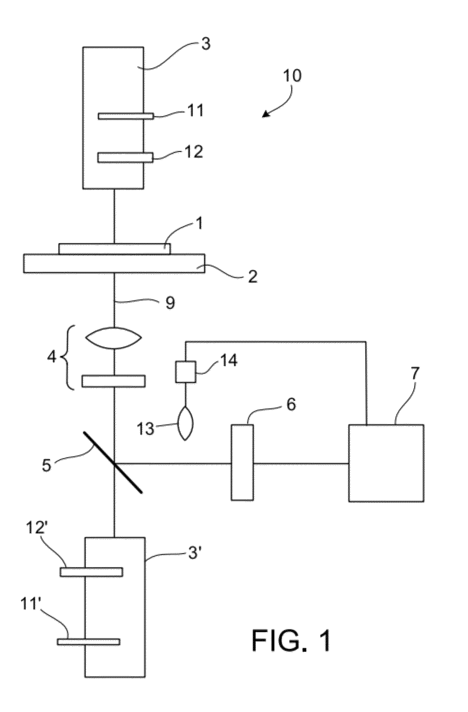
[0111]FIG. 1 depicts a position measuring device 10 that serves to measure the position of patterns on masks.

[0112]A mask 1 for photolithography is placed on a stage 2. The stage 2 can be moved in three spatial directions to position the mask 1. To ensure high accuracy, the current position or the path difference is monitored by means of laser interferometric or other high-precision measuring instruments (not shown). The mask 1 and the stage 2 are arranged horizontally; the mask plane is denoted the xy-plane. Disposed above the stage 2 with the mask 1 is an illumination device 3. This includes at least one illumination source emitting coherent illuminating light, which illuminates the mask via an illumination beam path. The illuminating light source can be embodied, for example, as a laser that emits light with a wavelength of 193 nm. The illumination device 3 serves to shine light through the mask 1. On the other side of the stage 2 is another illumination device 3′, which serves t...


PUM


Abstract

A method for determining a registration error of a feature on a mask, including providing a first aerial image that was captured by means of a position measuring device and includes at least the feature, simulating, from pattern specifications of the mask, a second aerial image that includes at least the feature, taking into account at least one effect that causes distortion of the first aerial image, and determining the registration error of the feature as the distance of the position of the feature in the first aerial image from the position of the feature in the second aerial image. Also provided is a method for simulating an aerial image from pattern specifications of a mask and a position measuring device for carrying out the method.

Description

CROSS REFERENCE TO RELATED APPLICATIONS[0001]Pursuant to 35 U.S.C. §119, this application claims the benefit of U.S. provisional application 61 / 381,700, filed Sep. 10, 2010 and German application DE 102010045135.5, filed Sep. 10, 2010. The above applications are incorporated by reference.BACKGROUND OF THE INVENTION[0002]This patent specification is directed to a method for determining a registration error of a feature on a mask.[0003]This patent specification is also directed to a method for simulating an aerial image from pattern specifications of a mask.[0004]The patent specification is also directed to a position measuring device for carrying out the method.[0005]In lithography for semiconductor component fabrication, the patterns of masks, which are also referred to synonymously as reticles, are projected by means of scanners or steppers onto wafers coated with a light-sensitive layer, the resist. Masks can be configured, for example, as “binary masks,” with chromium patterns on...

Claims


Application Information

Patent Timeline
IPC IPC(8): G06K9/00
CPCG01B11/00G03F1/84G03F1/42G01B11/26
Inventor ARNZ, MICHAELSEIDEL, DIRKKLOSE, GERD
Owner CARL ZEISS SMT GMBH
Why Eureka
Try Eureka