Wideband Interferometer Type Polarized Light Combiner and Splitter

a polarized light, interferometer-type technology, applied in the direction of optics, instruments, optical light guides, etc., can solve the problem of not being able to obtain the desired properties of polarized beam combining and splitting

Active Publication Date: 2012-03-15
NIPPON TELEGRAPH & TELEPHONE CORP
View PDF6 Cites 22 Cited by
  • Summary
  • Abstract
  • Description
  • Claims
  • Application Information

AI Technical Summary

Benefits of technology

[0027]When the present invention is employed, an interferometer type polarization beam combiner and splitter can be provided, which can combine and split polarized light across a wide wavelength range.

Problems solved by technology

However, when a manufacturing error occurs, desired properties for polarized beam combining and splitting can not be obtained.

Method used


Image

  • Wideband Interferometer Type Polarized Light Combiner and Splitter
  • Wideband Interferometer Type Polarized Light Combiner and Splitter
  • Wideband Interferometer Type Polarized Light Combiner and Splitter

Examples


example 1

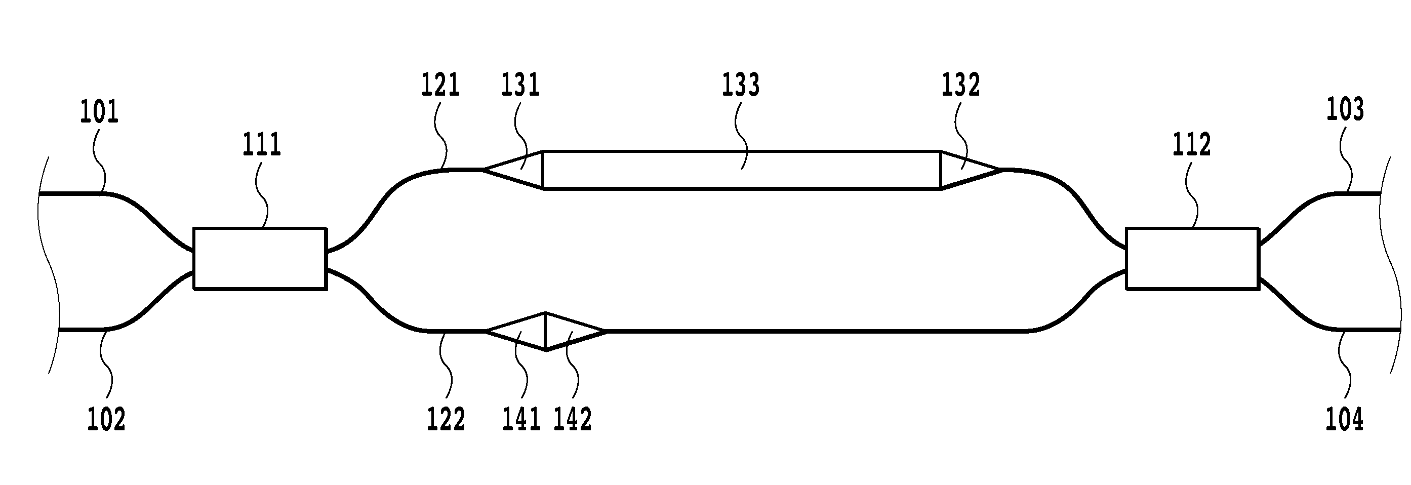
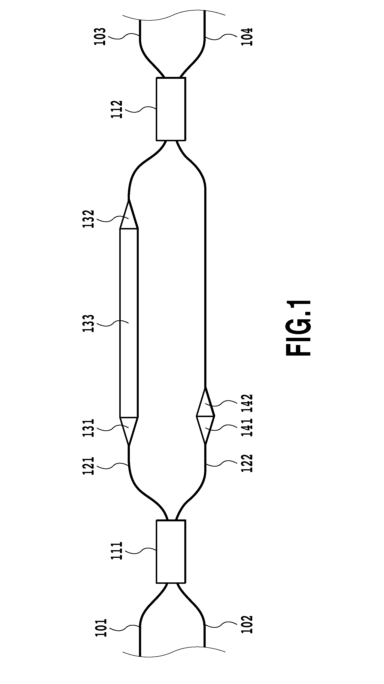
[0146]A wideband interferometer type polarization beam combiner and splitter according to example 1 is illustrated in FIG. 13A. In this example, a WINC is employed as an optical splitter and an optical coupler, and a WINC 314, serving as an optical splitter, and a WINC 315, serving as an optical coupler, are arranged symmetrically at the center of a circuit. Grooves 331 are formed in the vicinity of both sides of an optical waveguide 222 of an optical path length difference imparting unit, and differential birefringence is generated by releasing stress on the waveguide through the grooves. These grooves are called stress release grooves. Further, an element that changes the width of an optical waveguide is provided for the other optical waveguide 221 of the optical path length difference imparting unit, and is employed to generate a difference in refractive index dispersion. This element is called a width-varying waveguide 341. The means for generating differential birefringence and...

example 2

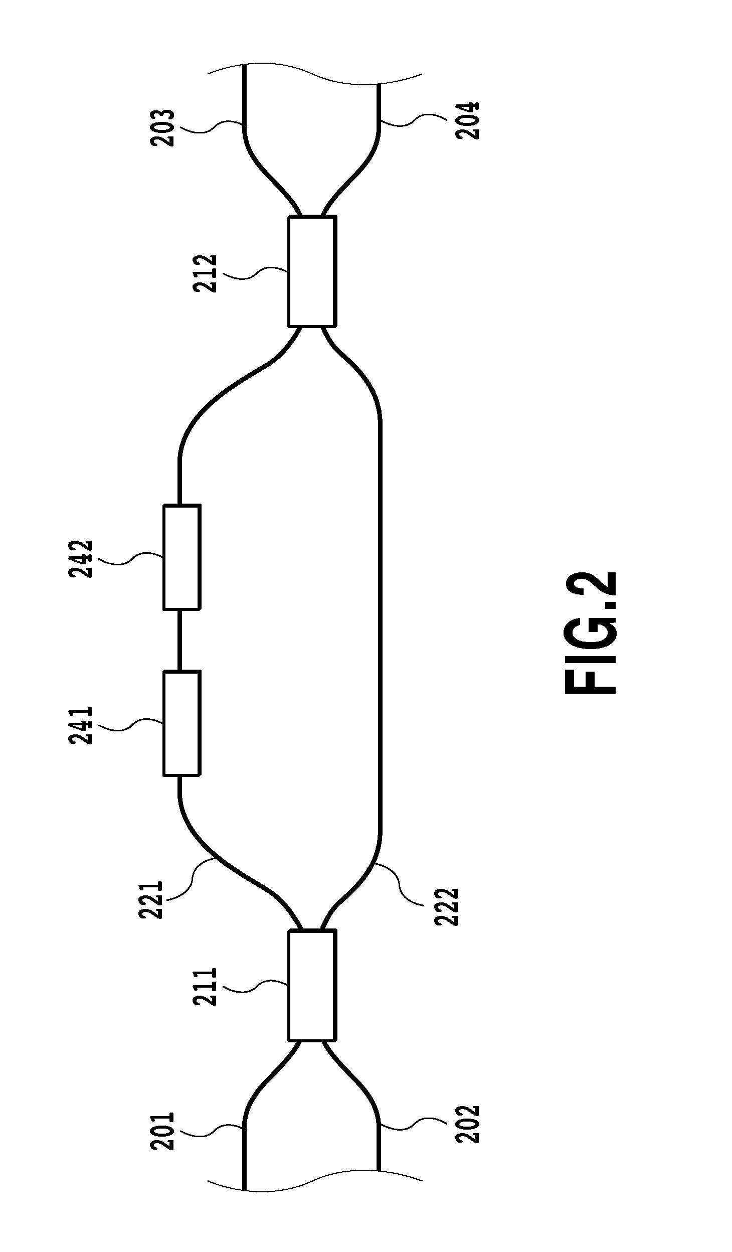
[0148]A wideband interferometer type polarization beam combiner and splitter according to example 2 is shown in FIG. 14. A difference in this example from example 1 is that a Y-branch splitter 313 is employed instead of a WINO, serving as an optical splitter, and the other arrangement is the same as that in example 1. Means for generating differential birefringence and means for generating a difference in refractive index dispersion are provided in order to satisfy equations (16) and (31).

[0149]Example numerical values will be specifically given below. The width of an optical waveguide is set as 4.5 μm. For the optical waveguides, except for the one for which either the means (a width-varying waveguide 341), for generating a difference in refractive index dispersion in an optical path length difference imparting unit, or the means (stress release grooves 331), for generating differential birefringence, is provided, an optical path length difference ΔL between an optical waveguide 22...

example 3

[0150]A wideband interferometer type polarization beam combiner and splitter according to example 3 is shown in FIG. 15A. A difference in this example from example 1 is that a plurality of means for generating differential birefringence are provided, and are located along different optical waveguides of an optical path length difference imparting unit, and the other arrangement is the same as that for example 1. In this example, as a second means for generating differential birefringence, extra optical waveguides are formed in the vicinity of both sides of an optical waveguide 221 of the optical path length difference imparting unit. This waveguide is called a birefringence adjustment waveguide 332. As shown in FIG. 15A, the birefringence adjustment waveguides 332 and a width-varying waveguide 341 may partially overlap each other. The means for generating differential birefringence and the means for generating a difference in refractive index dispersion are set to satisfy equations ...


PUM


Abstract

A interferometer type polarization beam combiner and splitter, which can combine or split polarized light over a wide band, is provided. The interferometer type polarization beam combiner and splitter includes: an optical splitter; an optical coupler; an optical path length difference imparting unit, which includes a plurality of optical waveguides arranged between the optical splitting unit and the optical coupling unit; one or two input/output ports connected to the optical splitter; and two input/output ports connected to the optical coupler. A half-integer of a wavelength of λc is set as a normalized phase difference, for the optical path length difference imparting unit, between two polarization states, and means for generating a difference in refractive index dispersion is provided between the optical waveguides of the optical path length difference imparting unit, so that the change rate of the transmittance with respect to wavelength is suppressed for the two polarization states.

Description

TECHNICAL FIELD[0001]The present invention relates to an interferometer type polarization beam combiner and splitter that splits, or combines, polarized light that has been input. More particularly, the present invention relates to a wideband interferometer type polarization beam combiner and splitter that suppresses wavelength dependency by setting, for two polarization states, the same rate at which a transmittance changes relative to a wavelength, and that performs a wideband operation while employing only one interferometer type optical circuit.BACKGROUND ART[0002]The circuit structure for a conventional interferometer type polarization beam combiner and splitter is shown in FIG. 1 (see patent literature 1). This interferometer type polarization beam combiner and splitter is a Mach-Zehnder interferometer that includes two optical couplers 111 and 112 and two optical waveguides 121 and 122. The operation of the Mach-Zehnder interferometer is changed as follows, depending on an op...

Claims


Application Information

Patent Timeline
Patent Type & Authority Applications(United States)
IPC IPC(8): G02B6/24
CPCG02B6/12023G02B6/12007
Inventor MIZUNO, TAKAYUKIGOH, TAKASHIYAMAZAKI, HIROSHIKAMEI, SHINKITOH, TSUTOMU
Owner NIPPON TELEGRAPH & TELEPHONE CORP
Why Eureka
Try Eureka