Hybrid universal distribution system comprising electrical, fluid, and communication functions

a technology of universal distribution system and communication function, applied in the direction of electrically conductive connection, coupling device connection, lift valve, etc., can solve the problems of high risk of error, tangle of cables and hoses, and plant structure confusion

Inactive Publication Date: 2012-03-15
BURKERT WERKE
View PDF18 Cites 46 Cited by
  • Summary
  • Abstract
  • Description
  • Claims
  • Application Information

AI Technical Summary

Benefits of technology

[0015]The commissioning of complex plants is greatly simplified by Plug and Play with the aid of the invention described here. A simple assembly without any special tools is possible.
[0016]Downtimes and maintenance times are minimized since, on the one hand, errors are avoided and, on the other hand, are easier to locate, and the individual components can be easily exchanged and pretested.
[0017]An advantage of the distributor system described here is that it allows installations to be standardized.
[0019]A surface with few raised and depressed portions of the universal distributor system makes cleaning easier. This system is suitable for applications in harsh environments. It may be implemented in a high degree of protection, for example IP68.
[0025]In a further development of the universal distributor system, provision is made for integration of one or more shutoff valves. This permits supply circuits to be formed in a simple manner.
[0026]The passive modules described here may be upgraded at any time to form active modules by including further functions such as field bus or diagnostics. This makes additional controlling possible.

Problems solved by technology

Frequently, a multitude of actuators are each connected with lines leading to a plurality of supply sources, which results in a confusing structure of the plants.
This easily creates a tangle of cables and hoses.
With this type of wiring system, there is a very high risk of error, while at the same time trouble-shooting is, of course, difficult and involved.
High installation costs are incurred.
Individual components can only be tested or pretested involving great expense.
In modern installation practice for plant engineering, distributor modules are therefore already made use of These distributor modules are limited to purely electrical functions.

Method used


Image

  • Hybrid universal distribution system comprising electrical, fluid, and communication functions
  • Hybrid universal distribution system comprising electrical, fluid, and communication functions
  • Hybrid universal distribution system comprising electrical, fluid, and communication functions

Examples


Embodiment Construction

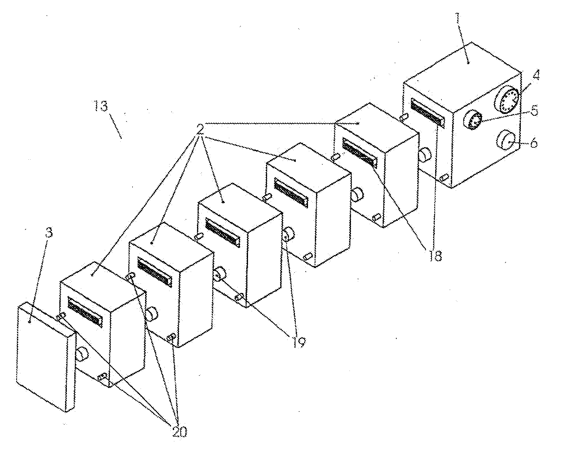
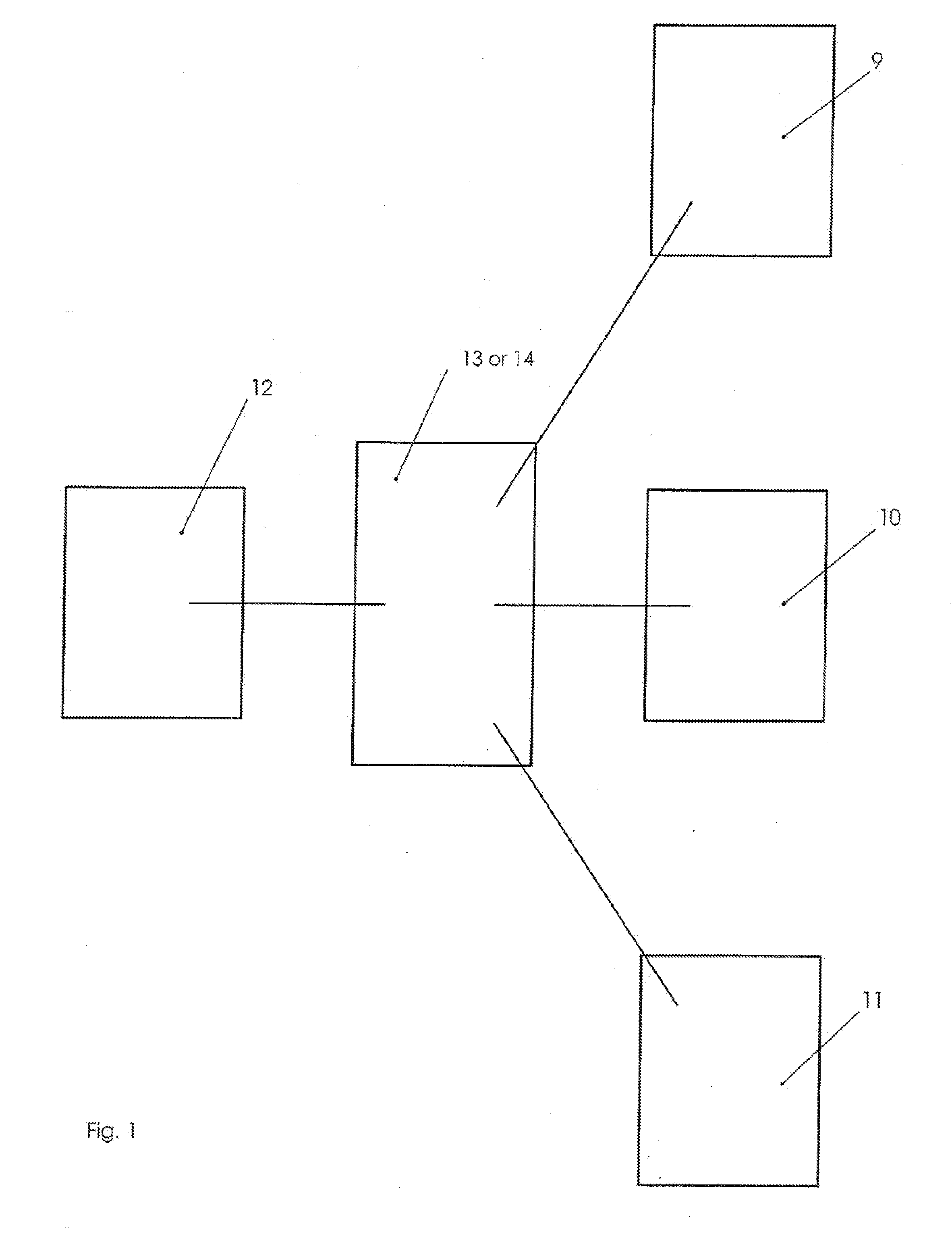
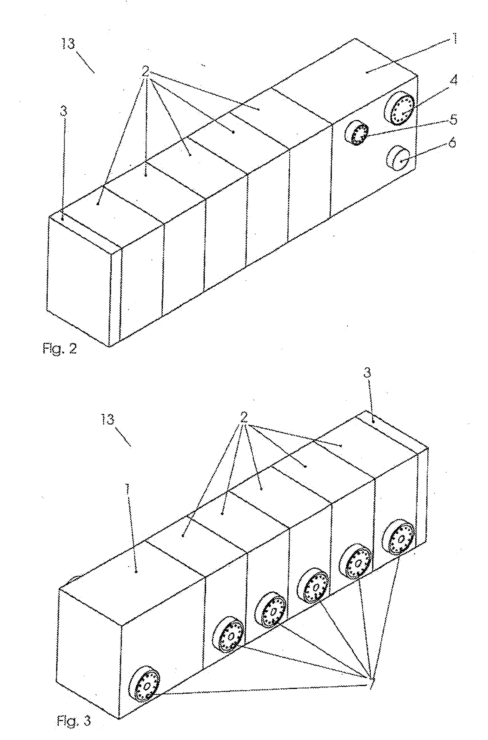
[0039]FIG. 1 schematically illustrates the organization of the universal distributor system according to the invention within an industrial plant. The universal distributor system 13 or 14 is connected to at least three functions such as compressed air supply 9, controlling means 10, and power supply 11. These three functions are brought together within the universal distributor system 13 or 14 and are jointly passed on to identical interfaces in the universal distributor system. An actuator 12 can now be connected to an interface of the universal distributor system by means of only one single hybrid cable; the actuator is supplied with electricity, compressed air, and communication signals via this interface.

[0040]When the stationary hybrid universal distributor system 14 is used, the maximum number of actuators that can be connected corresponds to the number of hybrid plugs 7 provided.

[0041]When employing the hybrid universal distributor system 13 having a modular structure, the n...


PUM


Abstract

A distributor for supplying consumers of an industrial plant with electricity and with fluid and for transmitting communication signals from and to the consumers has separate feed connections for supplying electricity and fluid as well as a collective line for communication signals. It further has a plurality of identical hybrid plug connectors which include plug connector elements for electric power supply, for fluid supply, and for communication signals and which are in communication with the corresponding feed connections and with the collective line, respectively.

Description

FIELD OF THE INVENTION[0001]The present invention relates to a distributor for supplying electricity and fluid to consumers of an industrial plant and for transmitting communication signals from and to the consumers.BACKGROUND OF THE INVENTION[0002]In plant construction in the most varied of industries such as pharmaceutical, chemical or food industries, devices at the actuator level such as, e.g., control valves are linked with supply systems (power supply, controlling means, compressed air) by complex installations. Frequently, a multitude of actuators are each connected with lines leading to a plurality of supply sources, which results in a confusing structure of the plants.[0003]Power and communication lines and hoses for compressed air or other fluids need to be laid over large distances and connected to the individual components using T-joints, for example. This easily creates a tangle of cables and hoses.[0004]With this type of wiring system, there is a very high risk of erro...

Claims


Application Information

Patent Timeline
Patent Type & Authority Applications(United States)
IPC IPC(8): H01R4/60
CPCF16L41/03H01R13/514H01R27/02H01R25/00H01R13/62H01R12/737Y10T137/87885
Inventor OTTLICZKY, MARTIN
Owner BURKERT WERKE
Why Eureka
Try Eureka