Gps/ins sensor fusion using GPS wind up model

Inactive Publication Date: 2012-03-15
CALIFORNIA INST OF TECH
View PDF2 Cites 36 Cited by
  • Summary
  • Abstract
  • Description
  • Claims
  • Application Information

AI Technical Summary

Benefits of technology

[0015]In yet another embodiment, the method of stabilizing an inertial navigation system further includes a GPS receiver having at least one GPS antenna which is present on a first vehicle, and a second GPS receiver having at least one GPS antenna is configured to perform the method of claim 1 on a second vehicle differen

Problems solved by technology

In present day GPS compensated INS systems, there are wind up errors su

Method used


Image

  • Gps/ins sensor fusion using GPS wind up model
  • Gps/ins sensor fusion using GPS wind up model
  • Gps/ins sensor fusion using GPS wind up model

Examples


Embodiment Construction

[0028]As described hereinabove, the phase wind up effect causes the carrier phase to advance as the GPS antenna rotates. This unique signature of the resolved ambiguity phase enables the observability and stabilization of the inertial navigation system yaw and yaw bias, states that are weakly observable without significant and time varying inertial acceleration. Enabling the use of carrier phase wind up models to correct the inertial errors is expected to have a significant impact on the production and use of low cost inertial systems for scientific and real time applications, since the yaw angle will now have an accuracy commiserate with the pitch and roll angles.

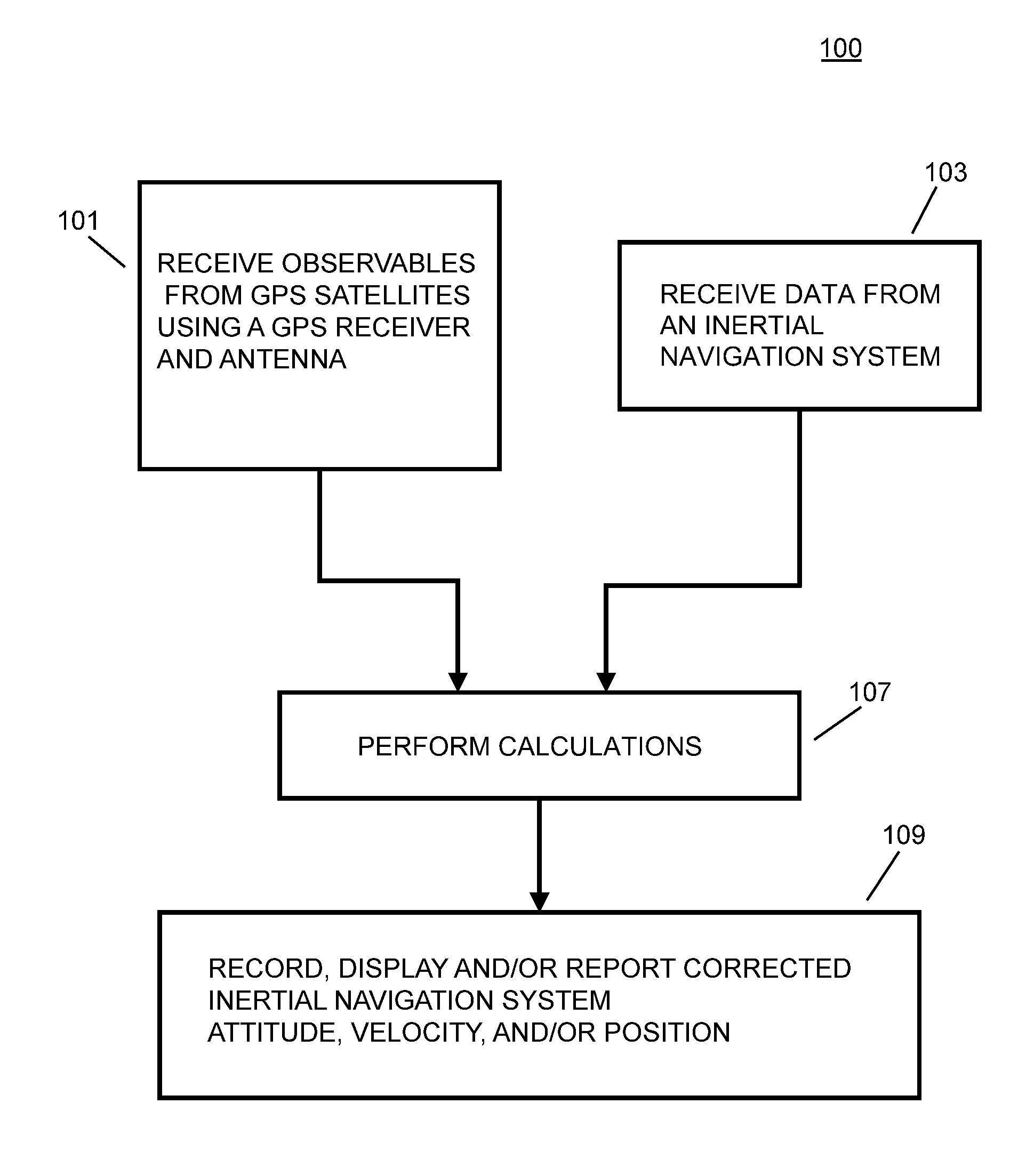
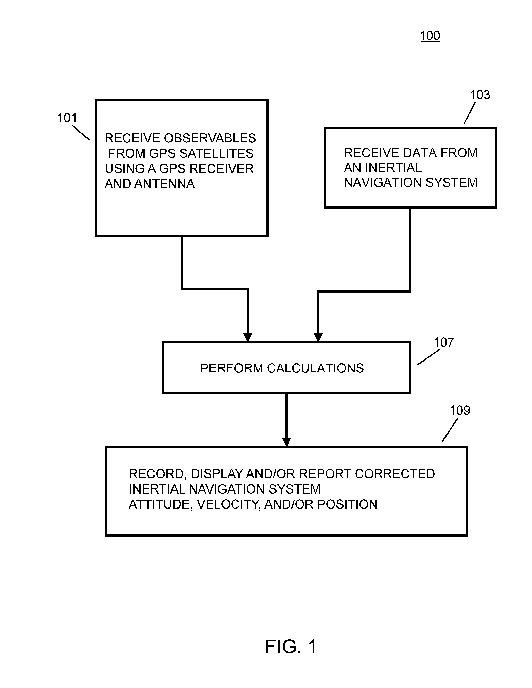
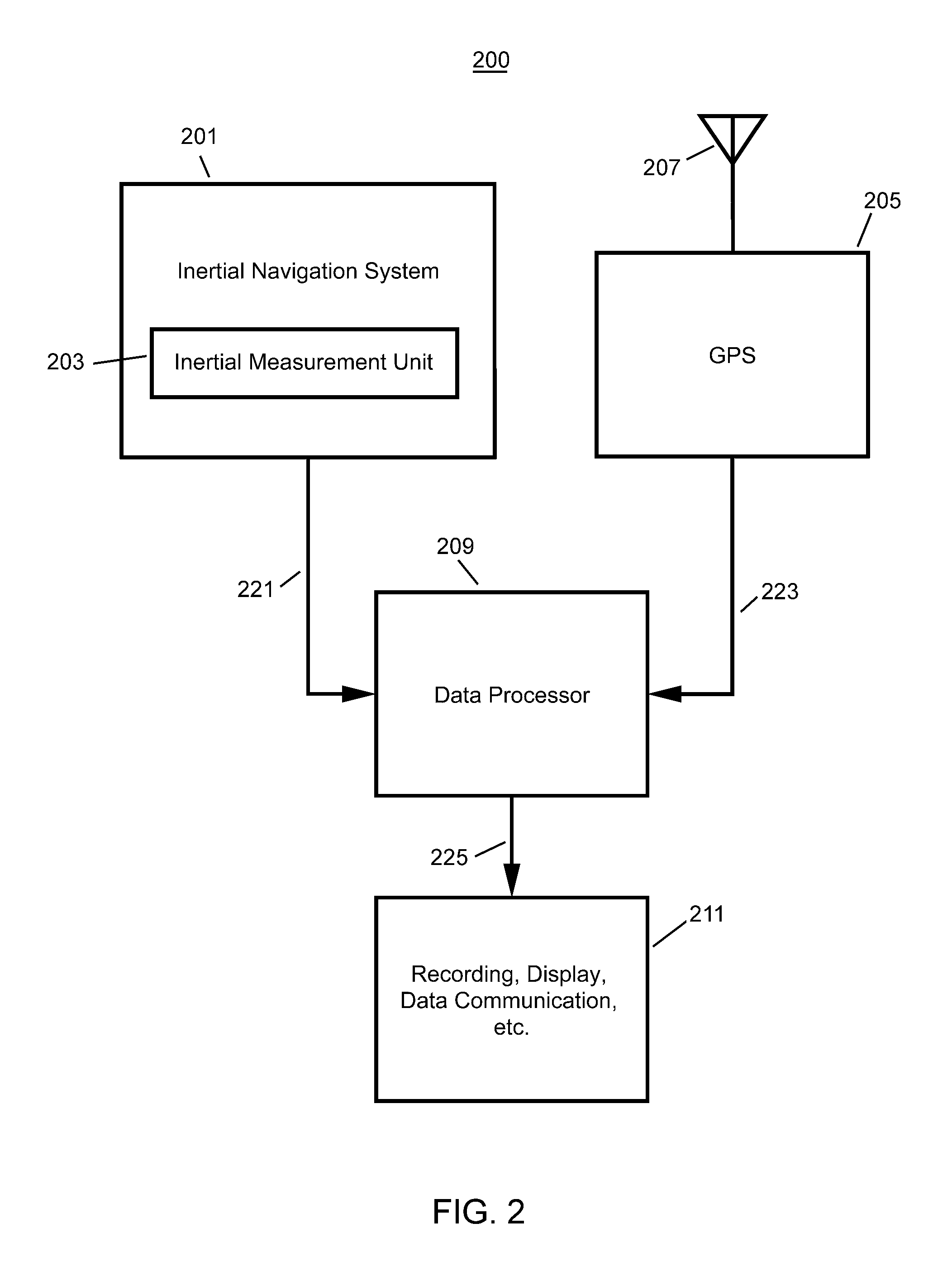
[0029]A system and method for using GPS carrier phase measurements to correct a navigation state generated by an inertial navigation system (INS) is described hereinbelow. In one exemplary embodiment, the method assumes at least one GPS receiver and one inertial navigation system operating on a single vehicle. The system a...


PUM


Abstract

A method of stabilizing an inertial navigation system (INS), includes the steps of: receiving data from an inertial navigation system; and receiving a finite number of carrier phase observables using at least one GPS receiver from a plurality of GPS satellites; calculating a phase wind up correction; correcting at least one of the finite number of carrier phase observables using the phase wind up correction; and calculating a corrected IMU attitude or velocity or position using the corrected at least one of the finite number of carrier phase observables; and performing a step selected from the steps consisting of recording, reporting, or providing the corrected IMU attitude or velocity or position to another process that uses the corrected IMU attitude or velocity or position. A GPS stabilized inertial navigation system apparatus is also described.

Description

CROSS-REFERENCE TO RELATED APPLICATIONS[0001]This application claims priority to and the benefit of co-pending U.S. provisional patent application Ser. No. 61 / 382,333, filed Sep. 13, 2010, which application is incorporated herein by reference in its entirety.STATEMENT REGARDING FEDERALLY FUNDED RESEARCH OR DEVELOPMENT[0002]The invention described herein was made in the performance of work under a NASA contract, and is subject to the provisions of Public Law 96-517 (35 USC 202) in which the Contractor has elected to retain title.FIELD OF THE INVENTION[0003]The invention relates to inertial navigation in general and particularly to an inertial navigation system that employs a GPS correction of inertial navigation system errors.BACKGROUND OF THE INVENTION[0004]Methods for compensating inertial navigation with GPS have been described, for example, by Williamson, et. al., in “Sensor Fusion Applied to Autonomous Aerial Refueling, Journal of Guidance, Control, and Dynamics,” Vol. 32, No. 1...

Claims


Application Information

Patent Timeline
IPC IPC(8): G01C21/10
CPCG01C21/165G01S19/47G01C21/188
Inventor WILLIAMSON, WALTON R.
Owner CALIFORNIA INST OF TECH
Why Eureka
Try Eureka