
Efficient Combined Harmonic Transposition

Active Publication Date: 2012-03-15
DOLBY INT AB
View PDF1 Cites 52 Cited by
  • Summary
  • Abstract
  • Description
  • Claims
  • Application Information

AI Technical Summary

Benefits of technology

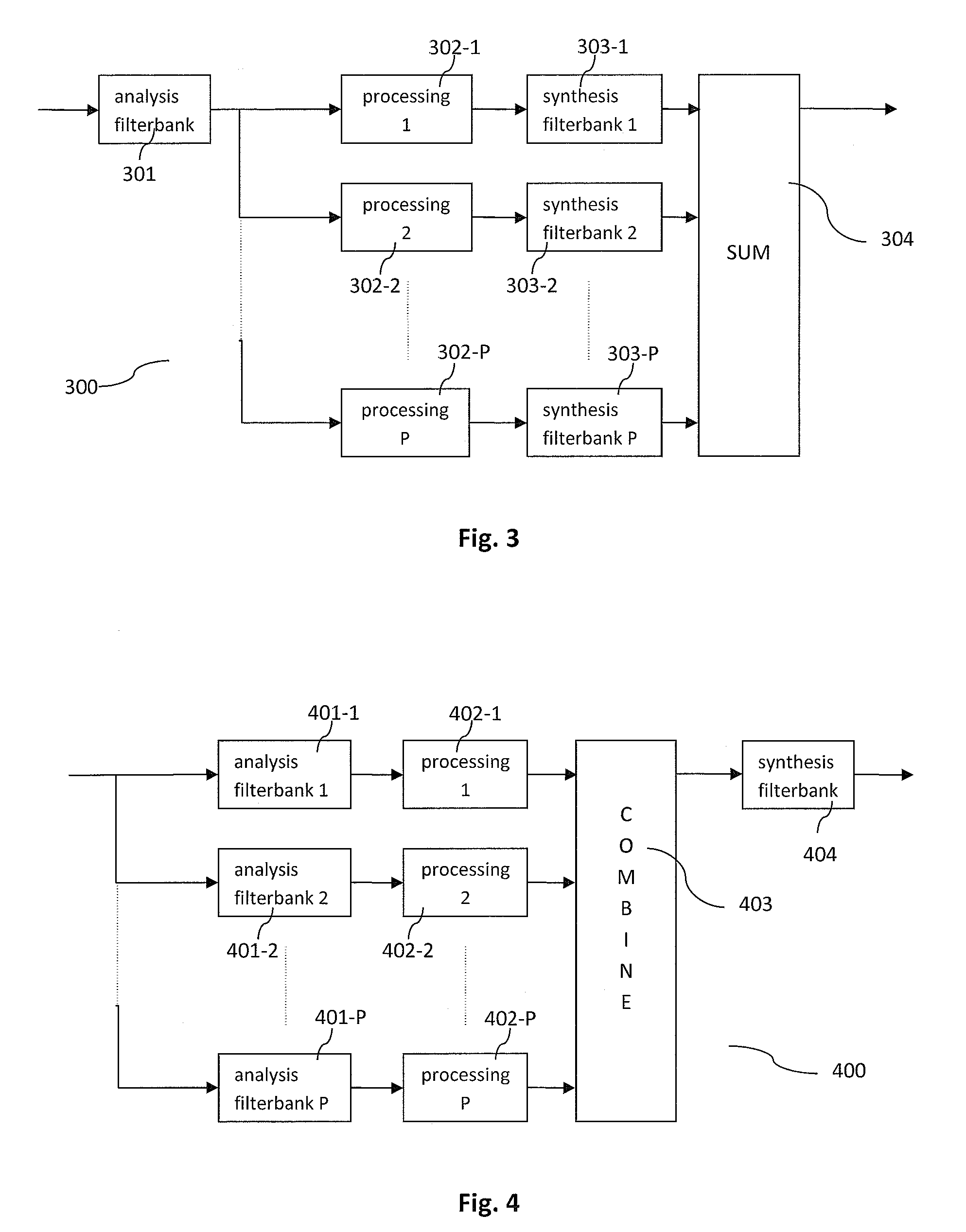
[0004]The present invention provides a method for reducing the complexity of harmonic HFR methods by means of enabling the sharing of an analysis and synthesis filter bank pair by several harmonic transposers, or by one or several harmonic transposers and an upsampler. The proposed frequency domain transposition may comprise the mapping of nonlinearly modified subband signals from an analysis filter bank into selected subbands of a synthesis filter bank. The nonlinear operation on the subband signals may comprise a multiplicative phase modification. Furthermore, the present invention provides various low complexity designs of HFR systems.

Problems solved by technology

Given a core signal with low bandwidth, i.e. a low band signal with a low upper frequency, a dissonant ringing artifact will typically result from the SSB transposition, which may therefore be disadvantageous compared to harmonic transposition.
All in all, the computationally complexity increases significantly with an increasing number of different transposition orders.

Method used


Image

  • Efficient Combined Harmonic Transposition
  • Efficient Combined Harmonic Transposition
  • Efficient Combined Harmonic Transposition

Examples


Embodiment Construction

[0053]The below-described embodiments are merely illustrative for the principles of the present invention for efficient combined harmonic transposition. It is understood that modifications and variations of the arrangements and the details described herein will be apparent to others skilled in the art. It is the intent, therefore, to be limited only by the scope of the impending patent claims and not by the specific details presented by way of description and explanation of the embodiments herein.

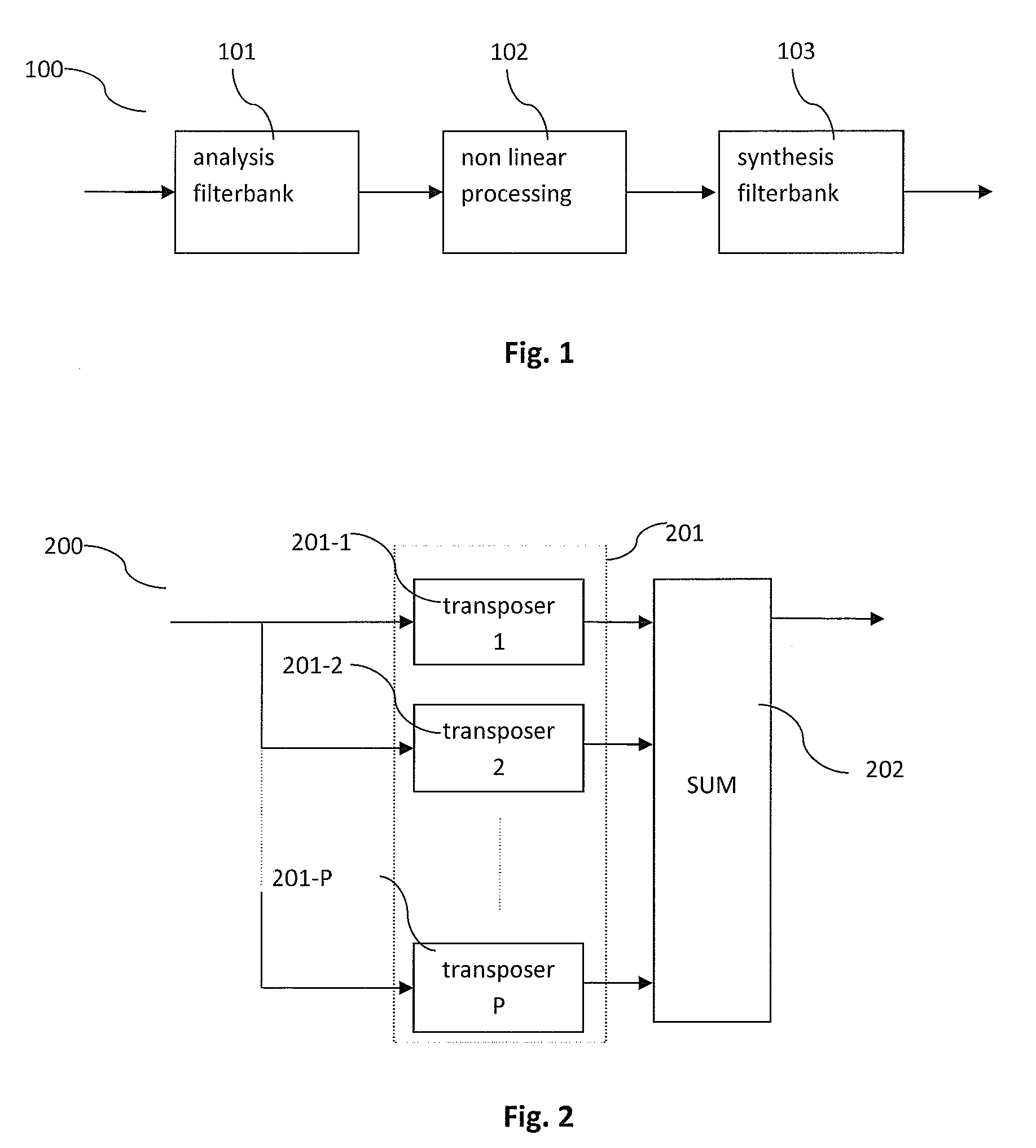
[0054]FIG. 1 illustrates the operation of a frequency domain (FD) harmonic transposer 100. In a basic form, a Tth order harmonic transposer is theoretically a unit that shifts all signal components of the input signal to a T times higher frequency. In order to implement such transposition in the frequency domain, an analysis filter bank (or transform) 101 transforms the input signal from the time-domain to the frequency domain and outputs complex subbands or subband signals, also referred t...


PUM


Abstract

The present document relates to audio coding systems which make use of a harmonic transposition method for high frequency reconstruction (HFR), and to digital effect processors, e.g. so-called exciters, where generation of harmonic distortion adds brightness to the processed signal. In particular; a system configured to generate a high frequency component of a signal from a low frequency component of the signal is described, The system may comprise an analysis filter bank (501) configured to provide a set of analysis subband signals from the low frequency component of the signal; wherein the set of analysis subband signals comprises at least two analysis subband signals; wherein the analysis filter bank (501) has a frequency resolution of Δf, The system further comprises a nonlinear processing unit (502) configured to determine a set of synthesis subband signals from the set of analysis subband signals using a transposition order P; wherein the set of synthesis subband signals comprises a portion of the set of analysis subband signals phase shifted by an amount derived from the transposition order P; and a synthesis filter bank (504) configured to generate the high frequency component of the signal from the set of synthesis subband signals; wherein the synthesis filter bank (504) has a frequency resolution of FΔf; with F being a resolution factor, with F≧1; wherein the transposition order P is different from the resolution factor F.

Description

TECHNICAL FIELD[0001]The present document relates to audio coding systems which make use of a harmonic transposition method for high frequency reconstruction (HFR), and to digital effect processors, e.g. so-called exciters, where generation of harmonic distortion adds brightness to the processed signal. In particular, the present document relates to low complexity methods for implementing high frequency reconstruction.BACKGROUND OF THE INVENTION[0002]In the patent document WO 98 / 57436 the concept of transposition was established as a method to recreate a high frequency band from a lower frequency band of an audio signal. A substantial saving in bitrate can be obtained by using this concept in audio coding. In an HFR based audio coding system, a low bandwidth signal, also referred to as the low frequency component of a signal, is presented to a core waveform coder, and the higher frequencies, also referred to as the high frequency component of the signal, are regenerated using signal...

Claims


Application Information

Patent Timeline
IPC IPC(8): G10L19/00
CPCG10L21/038G10L21/0388G10L19/02G10L19/00H03M7/30G10L19/265G10H1/0091G10H1/125G10H2210/311
Inventor EKSTRAND, PERVILLEMOES, LARSHEDELIN, PER
Owner DOLBY INT AB
Learn More